Grid for radiography and manufacturing method thereof, and radiation imaging system

Inactive Publication Date: 2012-03-01
FUJIFILM CORP
View PDF3 Cites 4 Cited by
  • Summary
  • Abstract
  • Description
  • Claims
  • Application Information

AI Technical Summary

Benefits of technology

[0024]The colloidal particles deposited on the front surface of the substrate are removed. This increases transmittance of the radiation through the radiation transmitting portions, and hence improves performance of the grid. Provision of the liquid repellent film on the

Problems solved by technology

Thus, to obtain the X-ray absorbing portions with the high aspect ratio, it is necessary to repeat the formation of the resist pattern and the embedment of the gold paste a quite number of times, and requires much time.
Therefore, it is di

Method used


Image

  • Grid for radiography and manufacturing method thereof, and radiation imaging system
  • Grid for radiography and manufacturing method thereof, and radiation imaging system
  • Grid for radiography and manufacturing method thereof, and radiation imaging system

Examples


Embodiment Construction

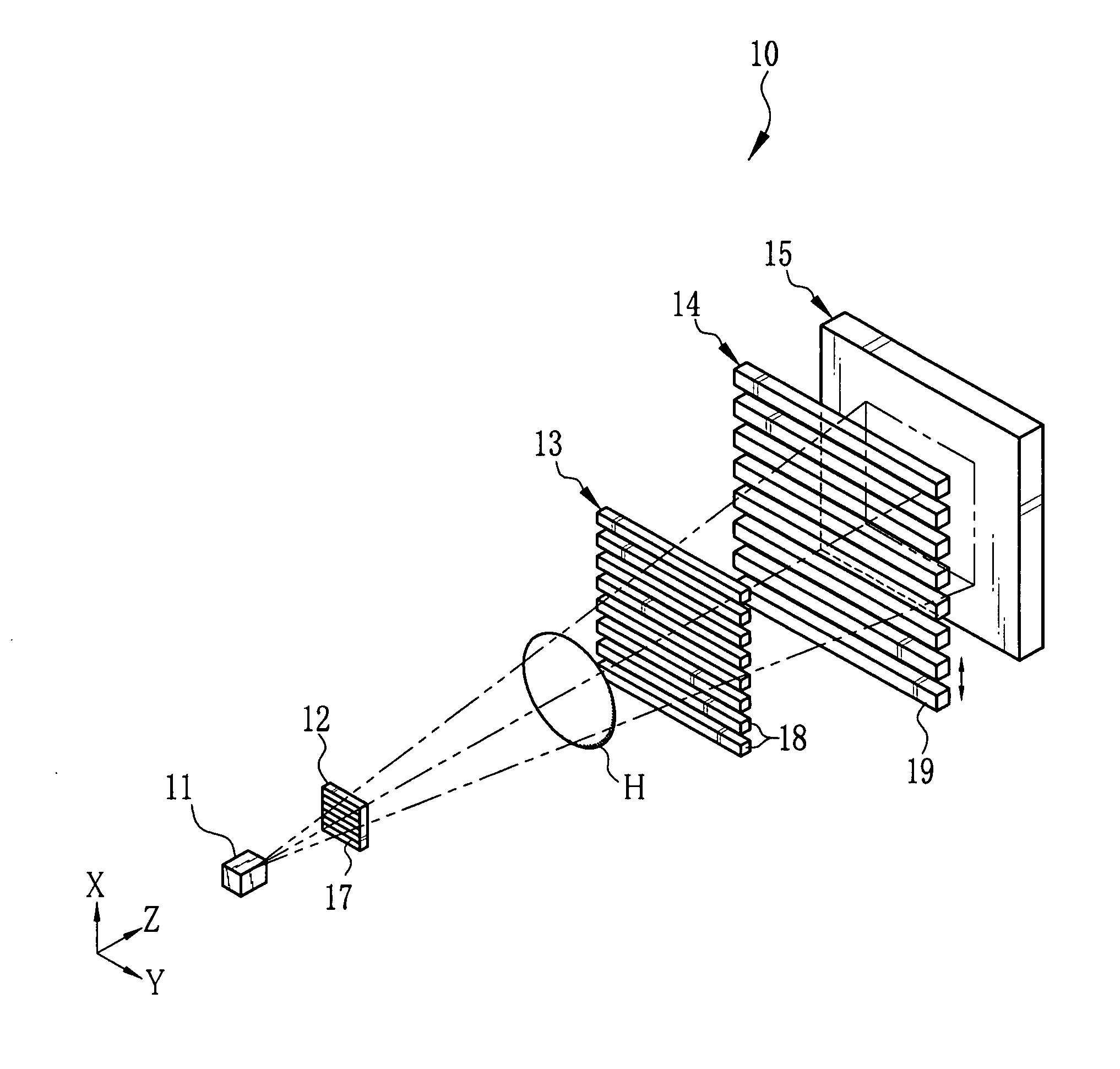
[0042]As shown in FIG. 1, an X-ray imaging system 10 according to the present invention is constituted of an X-ray source 11, a source grid 12, a first grid 13, a second grid 14, and an X-ray image detector 15. The X-ray source 11 applies an X-ray beam to a test object H disposed in a Z direction. The source grid 12 is opposed to the X-ray source 11 in the Z direction. The first grid 13 is disposed in parallel with the source grid 12 at a predetermined distance away from the source grid 12 in the Z direction. The second grid 14 is disposed in parallel with the first grid 13 at another predetermined distance away from the first grid 13 in the Z direction. The X-ray image detector 15 is opposed to the second grid 14. As the X-ray image detector 15, a flat panel detector (FPD) having semiconductor circuitry is used, for example.

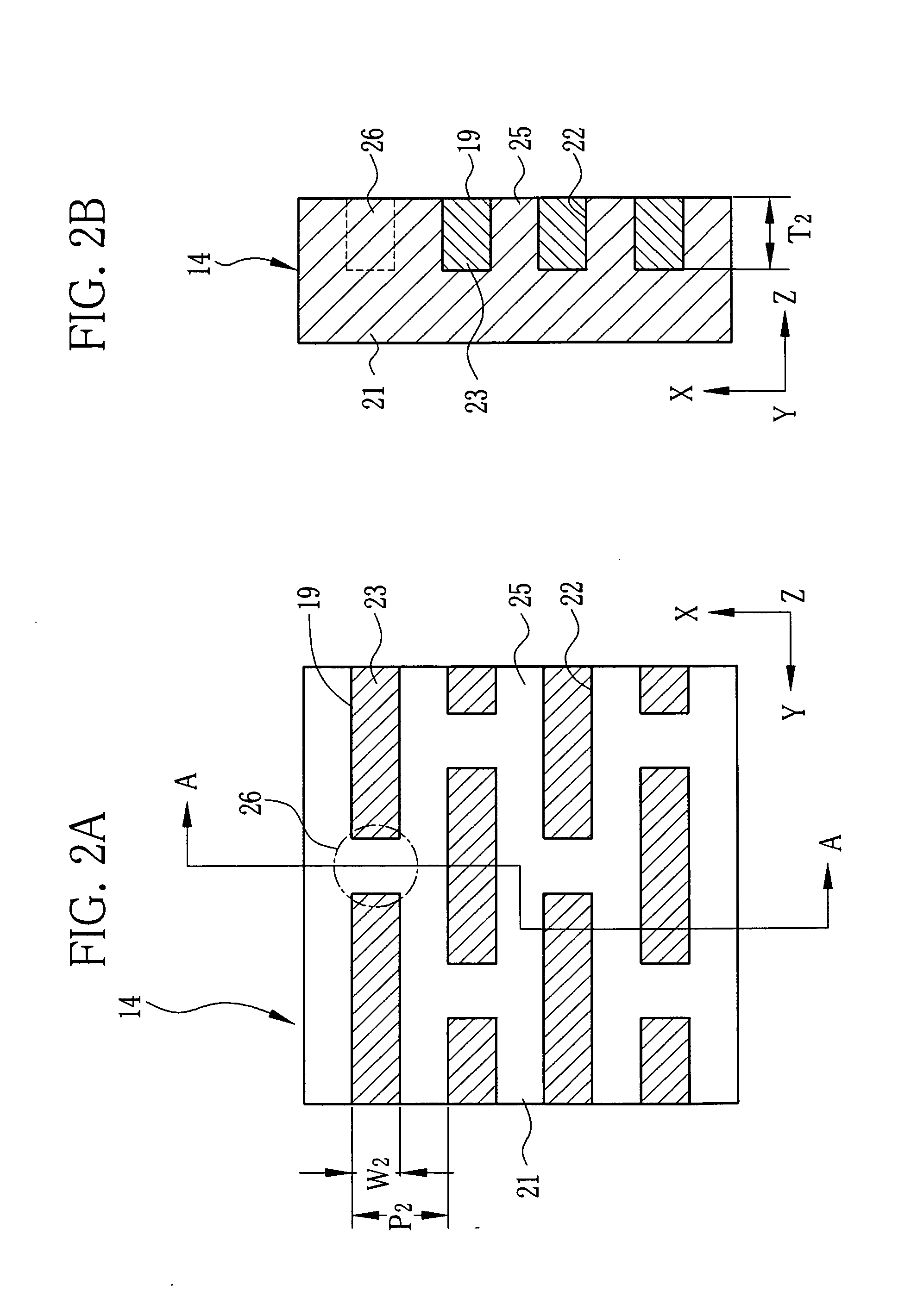
[0043]The source grid 12, the first grid 13, and the second grid 14 are X-ray absorption grids having plural X-ray absorbing portions 17, 18, and 19, respective...


PUM


Abstract

To produce a grid for radiography, grooves with a high aspect ratio are formed in an X-ray transparent substrate, and a colloidal gold solution is dripped into the grooves in such an amount that the colloidal gold solution does not overflow the grooves. The applied colloidal gold solution flows into the grooves by capillarity. The X-ray transparent substrate is heated from beneath by a laser beam at a portion charged with the colloidal gold solution. Thus, the colloidal gold solution is dried with leaving colloidal gold particles behind. The charging and drying of the colloidal gold solution are repeated, until the grooves are filled with the colloidal gold particles. The grooves and the colloidal gold particles compose X-ray absorbing portions of the grid.

Description

BACKGROUND OF THE INVENTION[0001]1. Field of the Invention[0002]The present invention relates to a grid used in radiography, a manufacturing method of the grid, and a radiation imaging system using the grid.[0003]2. Description Related to the Prior Art[0004]A radiation imaging system using the Talbot effect is devised to perform a type of radiation phase imaging, for obtaining an image (hereinafter called phase contrast image) based on phase change (angle change) of a radiation beam by passing through a test object. For example, an X-ray imaging system using an X-ray beam as the radiation beam has a first grid disposed behind the test object to be imaged, a second grid disposed downstream from the first grid in an X-ray beam direction, and an X-ray image detector disposed behind the second grid. The second grid is situated away from the first grid by a specific distance (Talbot distance), which is determined by a grid pitch of the first grid and a wavelength of the X-ray beam. The X...

Claims


Application Information

Patent Timeline
IPC IPC(8): G21K1/00G01N23/04H01L31/18
CPCA61B6/4035A61B6/4291G21K2207/005G21K1/02G21K1/06A61B6/484
Inventor KANEKO, YASUHISA
Owner FUJIFILM CORP
Why Eureka
Try Eureka