High Temperature Catalysts for Decomposition of Liquid Monopropellants and Methods for Producing the Same

a technology of liquid monopropellant and catalyst, which is applied in the direction of catalyst activation/preparation, metal/metal-oxide/metal-hydroxide catalyst, etc., can solve the problems of excessive sintering of catalyst, void formation, and ineffectiveness of conventional catalyst applied to these formulations, and achieve excellent thermal shock resistance, high mechanical, chemical and thermal stability, good compatibility

Inactive Publication Date: 2012-05-10
SIENNA TECH
View PDF2 Cites 5 Cited by
  • Summary
  • Abstract
  • Description
  • Claims
  • Application Information

AI Technical Summary

Benefits of technology

[0009]The ceramic catalyst carriers of the present invention are modified high temperature perovskite-based ceramics with high mechanical, chemical and thermal stability in the rocket engine environment and therefore are suitable for preparation of catalysts for the decomposition of ionic salt (including HAN-based) monopropellants. The ceramic catalyst carriers of the present invention have various advantages, particularly when compared to previous materials, including excellent thermal shock resistance, good compatibility with catalytically active coatings (e.g., active metal coatings) and coating deposition processes, high melting points that are well above 2000° C., chemical resistance to steam, nitrogen oxides and nitric acid, resistance to sintering to prevent void formation, and the absence of phase transitions associated with volumetric changes at temperatures up to and greater than 1800° C.
[0010]In one embodiment, the present invention provides ceramic catalyst carriers comprising an alkaline-earth perovskite having the formula ABO3, wherein A is magnesium, calcium, strontium, or barium or combinations thereof and B is zirconium or hafnium, in which excess B cations (zirconium or hafnium cations) are added to form a secondary B cation-rich phase with high corrosion resistance in acidic and steam-rich environments.

Problems solved by technology

The high-adiabatic-decomposition-temperatures of the described HAN-based ionic salt monopropellants render conventional catalysts ineffective when applied to these formulations.
Problems observed during rocket engine tests containing conventional catalysts with new monopropellants include excessive sintering of catalyst, void formation, increase in pressure drop, fracturing of catalyst granules, fine formation, fragmentation of the catalyst granules due to thermal shock, leaching of the catalyst by acids, and rapid loss of catalyst activity.

Method used


Image

  • High Temperature Catalysts for Decomposition of Liquid Monopropellants and Methods for Producing the Same
  • High Temperature Catalysts for Decomposition of Liquid Monopropellants and Methods for Producing the Same
  • High Temperature Catalysts for Decomposition of Liquid Monopropellants and Methods for Producing the Same

Examples


example 1

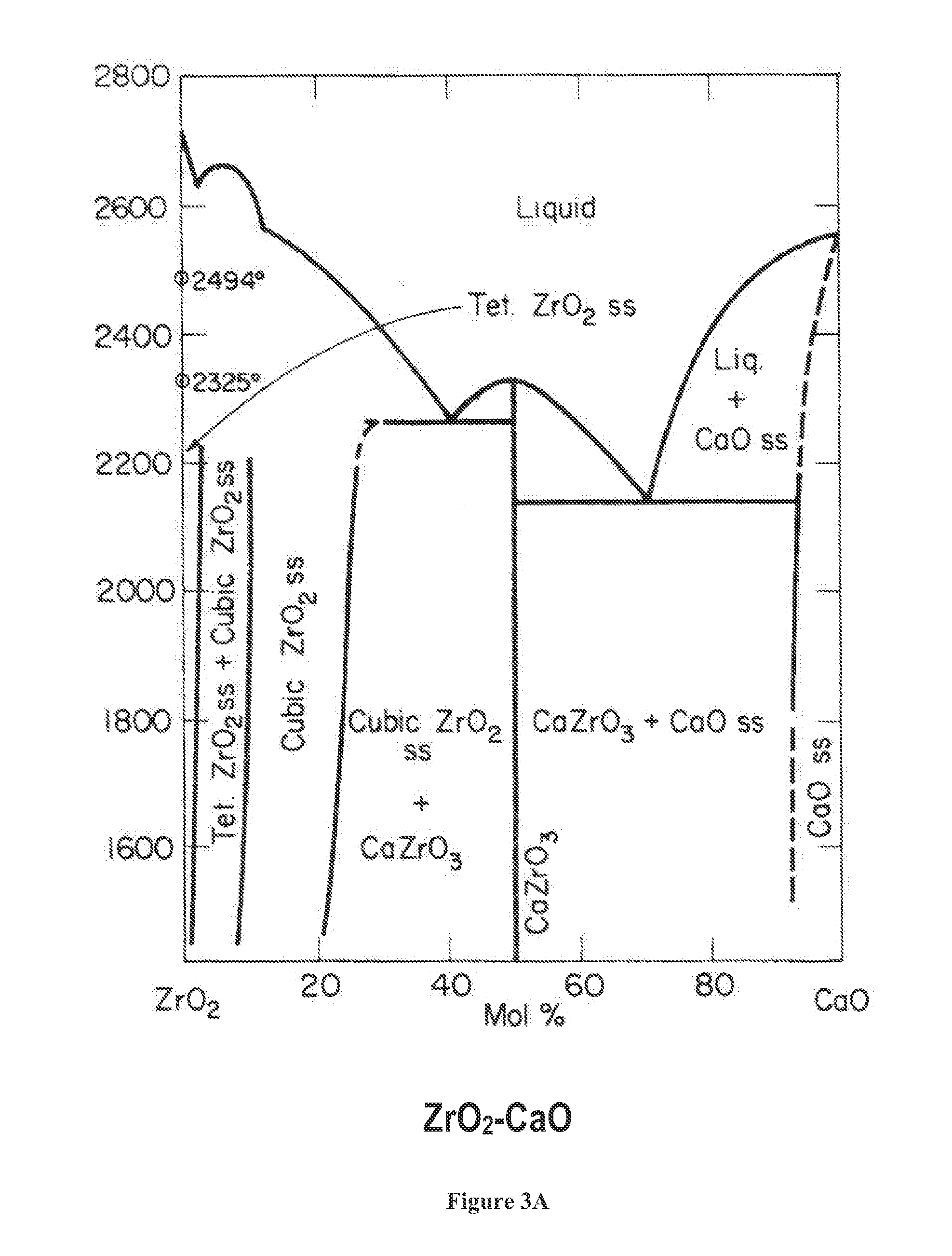
Production of CaZr1+yO3+2y Granules Where y=0.1, Using Flash-Freeze Process and Reactive Sintering

[0067]Necessary amounts of CaCO3 and ZrO2 powders to give a mole ratio of Ca / Zr=1.1 and total solids loading of 16% vol were dispersed in water by ball-milling using an ammonium polyacrylate type dispersant. After milling is complete, a water-soluble binder such as polyvinyl alcohol was added to the slurry at a concentration of 3.0% by weight to the powder (solids). The milled slurry was dispensed into a cold hexane bath held at a temperature of −60° C. using a spray atomizer and feed pressure of 2 psi while keeping the spray nozzle at least 2 cm above the height of the hexane. The flash-frozen granules were then removed from the hexane and placed in a freeze-dryer sample chamber held at a temperature of −20° C. to insure the granules did not melt. The pressure inside the freeze-dryer chamber was reduced to 1400° C. to facilitate reactive sintering and formation of ceramic granules with...

example 2

Coating of CaZr1.1O3.2 Granules with Iridium (Ir)

[0068]The CaZr1.1O3.2 granules produced in accordance with Example 1 herein above were coated with iridium (Ir) via wet deposition using a dihydrogen hexachloroiridic acid solution to give a loading of 5%-10% by weight Ir. The Ir—CaZr1.1O3.2 catalyst was subject to engine fire tests with a HAN-based ionic salt propellant and ignited 10 lbm of propellant in random sequences of 0.1 sec-20 sec duration pulses and survived >1,000 pulses with an accumulative fire time of >7 minutes (Zuttarelli, A., Gabrang, G., Gumulak, P., Moore, J., Zankich, V., Sawhill, S., “AFRL Advanced Monopropellant Risk Reduction (AMRR) Effort for Ionic Liquids,” 57th JANNAF Propulsion Conference, Colorado Springs, Colo., May 2010).

example 3

Production of CaZr1+yO3+2Y granules where y=0.85, using flash-freeze process and reactive sintering and coating of said granules with iridium (Ir).

[0069]CaZr1.85O4.7 granules were produced using the procedure set forth in Example 1 above except that the slurry contained necessary amounts of CaCO3 and ZrO2 powders to give a mole ratio of Ca / Zr=1.1.85. No other significant changes were made to the said procedure. The CaZr1.85O3.2 granules were coated with iridium (Ir) via wet deposition using the same procedure described in Example 2 above. The Ir—CaZr1.85O4.7 catalyst was subject to engine fire tests with a HAN-based ionic salt propellant and demonstrated an accumulative fire time of >30 minutes.


PUM

PropertyMeasurementUnit
Temperatureaaaaaaaaaa

Abstract

Ceramic catalyst carriers that are mechanically, thermally and chemically stable in a ionic salt monopropellant decomposition environment, high temperature catalysts for decomposition of liquid high-energy-density monopropellants and ceramic processing techniques for producing spherical catalyst carrier granules are disclosed. The ceramic processing technique is used to produce spherical catalyst carrier granules with controlled porosities and desired composition and allows for reproducible packing densities of catalyst granules in thruster chambers. The ceramic catalyst carrier has excellent thermal shock resistance, good compatibility with the active metal coating and metal coating deposition processes, melting point above >2300° C., chemical resistance to steam, nitrogen oxides and nitric acid, resistance to sintering to prevent void formation, and the absence of phase transition associated with volumetric changes at temperatures up to and beyond 1800° C.

Description

GOVERNMENT SUPPORT[0001]This invention was in part made with government support under Contract Nos. F04611-00-0030 and F04611-02-C-0006 awarded by the United States Air Force (AFRL). The Government has certain rights in the invention.FIELD OF THE INVENTION[0002]This invention relates generally to high temperature catalysts for decomposition of liquid high-energy-density ionic salt monopropellants and methods for producing the same.BACKGROUND OF THE INVENTION[0003]Reduced toxicity high-energy-density ionic salt monopropellants, including but not limited to monopropellants containing an oxidizer such as hydroxylammonium nitrate (HAN, [HO—NH3+]NO3−) and one or more fuels in highly concentrated solutions containing water, ethanol or a suitable solvent or without a solvent are being investigated as potential replacements for hydrazine-based propellants. The new monopropellants, which will hereinafter sometimes be referred to as ionic salt monopropellants or high-energy-density ionic salt...

Claims


Application Information

Patent Timeline
IPC IPC(8): B01J32/00C01G27/02B29C35/02B01J37/30B01J37/02C01G25/02B01J21/06
CPCB01J23/007B01J23/40C04B35/01B01J35/1019B01J37/0215B01J23/468C04B35/48C04B38/00C04B2111/0081C04B2235/3206C04B2235/3208C04B2235/3213C04B2235/3244C04B2235/444C04B2235/606B01J35/615C04B38/067B01J21/066B01J21/10B01J23/002B01J23/02
Inventor SAVRUN, ENDERSAWHILL, STEPHANIE J.
Owner SIENNA TECH
Why Eureka
Try Eureka