
Controlled Spark Ignited Flame Kernel Flow in Fuel-Fed Prechambers

Active Publication Date: 2012-05-24
WOODWARD GOVERNOR CO
View PDF6 Cites 79 Cited by
  • Summary
  • Abstract
  • Description
  • Claims
  • Application Information

AI Technical Summary

Benefits of technology

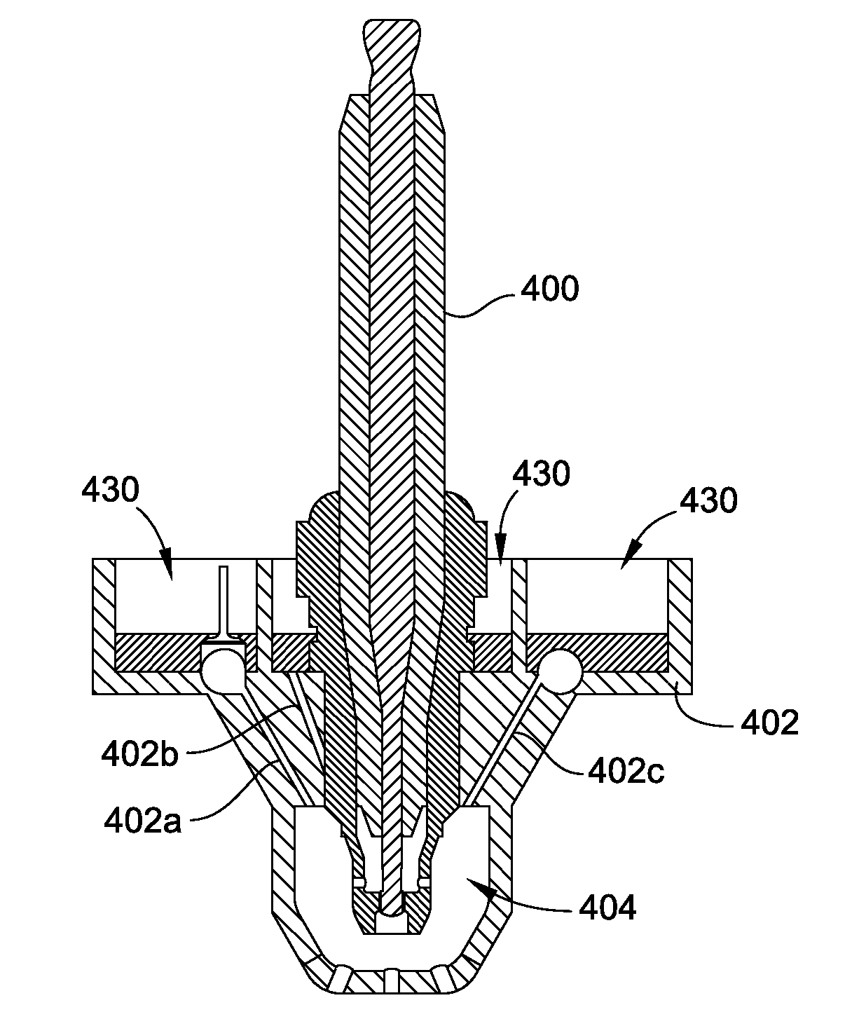
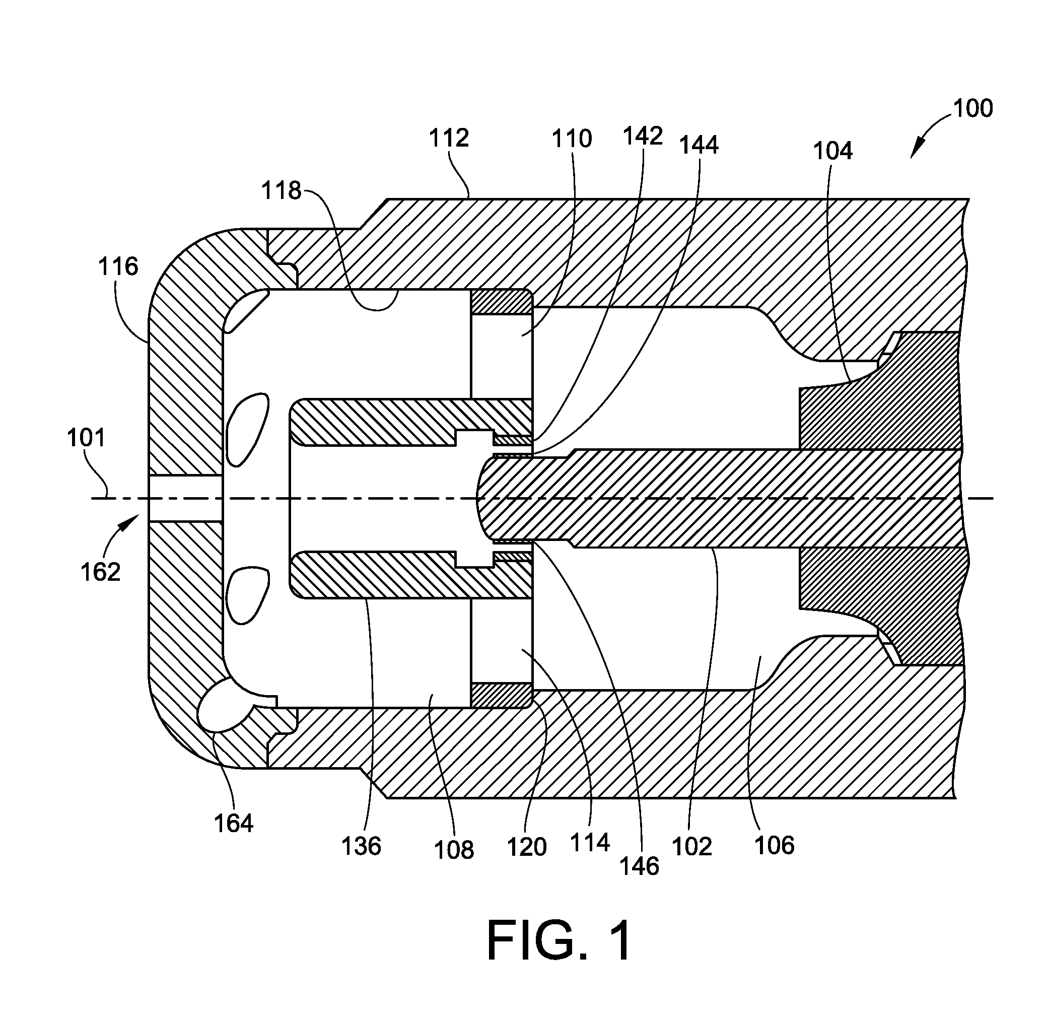
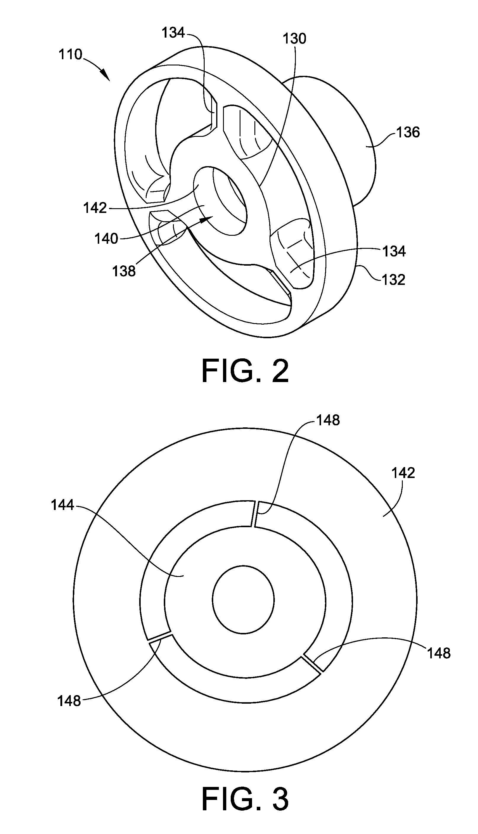
[0009]In one aspect, embodiments of the invention provide a pre-chamber spark plug that includes a shell, and an end cap attached to the shell, a center electrode and ground electrode. Additionally, the pre-chamber spark plug includes an insulator disposed within the shell. In a particular embodiment, the center electrode has a first portion surrounded by the insulator, and a second portion that extends from the insulator into a pre-chamber. The pre-chamber volume is defined by the shell and end cap. In a further embodiment, the ground electrode is attached to the shell. In particular embodiments, the ground electrode includes an inner ring spaced in surrounding relation to the center electrode, an outer ring attached to the shell, and a plurality of spokes connecting the inner and outer rings. In a particular embodiment, the ground electrode has a tubular shape which serves to protect the incoming central hole flow (primary) passing through the gap between the center and ground electrode from disturbances from the flow entering via lateral (secondary) holes. The tubular shape also directs the lateral hole flow behind the ground electrode at the periphery to join the spark kernel as it exits the gap. Additionally, the center electrode has an aerodynamic shape which improves the flow stream line through the gap from the center hole.
[0010]In another aspect, embodiments of the invention provide a method of facilitating combustion in an internal combustion engine. The method includes igniting an air / fuel mixture in a pre-chamber of a pre-chamber spark plug. In a particular embodiment, igniting an air / fuel mixture in a pre-chamber includes providing a first port to permit the flow of a first amount of air / fuel mixture into a gap between the center and ground electrode with a predominant backward flow direction from the front chamber of the pre-chamber, and igniting the air / fuel mixture in the gap, wherein the ignition produces a flame kernel. Further, the method includes causing the flame kernel to be transported to a back chamber of the pre-chamber, and providing a second port to permit the flow of a secondary (Lateral) amount of air / fuel mixture into the front chamber, such that the secondary amount of air / fuel mixture flows to the back chamber to be ignited by the flame kernel. The secondary flow may also have swirl which serves to spread the developing flame in the back chamber in the azimuthal direction—such that azimuthal uniformity is improved and generate turbulence within the pre-chamber which further speed combustion. The ignition of the first and second amounts of air / fuel mixture creates a pressure rise in the pre-chamber which causes a flame jet to issue from the first and second ports. The port hole size and angle can be optimized to maximize the flame jet velocity and penetration into the main chamber, thus enhancing combustion in the main chamber. The hole size controls both the inflow and outflow and thus is optimized to achieve the desired engine specific ignition delay time, jet velocity, and flame jet penetration and thus main chamber combustion rates.
[0013]The method also includes attachment of precious metal (or Noble Metal) to the center electrode and to the ground electrode which represents the sparking surface. The method also includes the manufacturing process whereby the gap between the center electrode and the ground electrode is created with a gapping tool during manufacturing and assembly such that the gap is determined accurately during manufacturing and assembly—thus reducing the need for re-gapping after fabrication. In one embodiment, the gapping tool is inserted between the center electrode and the ground electrode prior to final attachment of the ground electrode to the shell. This gap is best maintained if this is the final heating step in the process. In another embodiment, the spark gap is created after attachment of the ground electrode via electron beam (EB), water jet, or other suitable material removal method to create a precise high tolerance gap. The ideal new plug gap ranges from 0.15 mm to 0.30 mm
[0018]Another embodiment uses a laser light beam focused at a location between the gap surfaces, instead of an electric spark, to heat the AFR to ignition temperatures and create a flame kernel with photons instead of electrons. This embodiment includes a means to bring the light beam into and focus it into the gap region. The benefit of laser beam ignition is that it is far less sensitive to cylinder pressure conditions, where as an electric spark requires higher voltage to achieve break-down and spark as the pressure increases. The laser ignition method enables ignition at pressures above the break-down voltage limits of conventional electric ignition systems.

Problems solved by technology

The lean fuel mixture often results in poor combustion such as misfires, incomplete combustion and poor fuel economy and often efforts to improve combustion lead to detonation or the use of high energy spark that leads to short spark plug life.
One factor that can lead to such events is the poor ability of conventional spark plugs to effectively and consistently ignite a lean fuel mixture in the cylinder of the operating engine.
Many conventional pre-chamber spark plugs have non-repeatable and unpredictable performance characteristics which may lead to a higher than desired coefficient of variation (COV) and misfire, which is a measure of roughness.
Further, many conventional pre-chamber spark plugs are sensitive to manufacturing variation and suffer from poor burned gas scavenging, which further leads to increased COV.
One of the challenges in spark plug design is to create a plug capable of achieving a repeatable and controllable ignition delay time during the combustion process, in spite of the fact that, in internal combustion engines, the fresh charge will not usually be homogeneous or repeatable from cycle to cycle in many aspects (e.g., equivalence ratio, turbulence, temperature, residuals).
Another challenge in spark plug design is premature spark plug wear.
Typically, premature spark plug wear is caused by a high combustion temperature of the stoichiometric mixture.
This can lead to unscheduled downtime for the engine and therefore increased operational costs for the engine operator.

Method used


Image

  • Controlled Spark Ignited Flame Kernel Flow in Fuel-Fed Prechambers
  • Controlled Spark Ignited Flame Kernel Flow in Fuel-Fed Prechambers
  • Controlled Spark Ignited Flame Kernel Flow in Fuel-Fed Prechambers

Examples


Embodiment Construction

[0038]To address the issues of a repeatable and controllable ignition delay time during the combustion process, which results in both a more efficient combustion process and longer life for the spark plug, a pre-chamber spark plug has been developed that incorporates a tubular electrode to control the flame kernel development, ignition delay time, flame jet evolution, main combustion chamber burn rate, and consequently improves engine performance. The delay time is the period between the spark and that time when the combustion affects a volume sufficient to increase the pressure in the pre-chamber and in turn the main combustion chamber.

[0039]FIG. 1 illustrates a cross-sectional view of a portion of a pre-chamber spark plug 100, according to an embodiment of the invention. The pre-chamber spark plug 100 has a longitudinal axis 101 and a center electrode 102 that extends along the longitudinal axis 101, and further extends from an insulator 104 into a pre-combustion chamber that is d...


PUM


Abstract

A pre-chamber spark plug that includes a shell. Additionally, the pre-chamber spark plug includes an insulator disposed within the shell. In a particular embodiment, a center electrode has a first portion surrounded by the insulator, and a second portion that extends from the insulator into a pre-chamber. The pre-chamber defined by the shell. In a further embodiment, a ground electrode is attached to the insulator. In particular embodiments, the ground electrode is tubular in shape and includes an inner spark surface ring spaced in surrounding relation to the center electrode to create a spark gap, an outer ring attached to the shell, and a plurality of rounded spokes connecting the inner and outer rings. In a particular embodiment, the ground and center electrodes accommodate attachment of precious metal alloys to increase electrode surface life. In another embodiment the ground electrode and insulator is coaxial to the center electrode.

Description

CROSS-REFERENCE TO RELATED PATENT APPLICATIONS[0001]This patent application is a Continuation-in-Part of co-pending U.S. patent application Ser. No. 13 / 042,599, filed Mar. 8, 2011, which claims the benefit of U.S. Provisional Patent Application No. 61 / 416,588, filed Nov, 23, 2010, the entire teachings and disclosure of which are incorporated herein by reference thereto.FIELD OF THE INVENTION[0002]This invention generally relates to spark plugs for internal combustion engines, and, more particularly, to spark plugs having a pre-combustion chamber, or pre-chamber.BACKGROUND OF THE INVENTION[0003]Engines operating on gaseous fuels, such as natural gas, are commonly supplied with a lean fuel mixture, which is a mixture of air and fuel containing a excess air beyond that which is “chemically correct” or stoichiometric. The lean fuel mixture often results in poor combustion such as misfires, incomplete combustion and poor fuel economy and often efforts to improve combustion lead to detona...

Claims


Application Information

Patent Timeline
IPC IPC(8): F02B19/12F02B19/16
CPCY02T10/125F02B19/12F02B19/16F02P13/00H01T13/54F02P9/007H01T13/32Y02T10/12F02P15/001F02P21/02F02P23/04
Inventor CHIERA, DOMENICOPETRUSKA, DAVID C.HAMPSON, GREGORY JAMES
Owner WOODWARD GOVERNOR CO
Learn More