Binder resin composition for electrode, electrode mixture paste, and electrode

Active Publication Date: 2012-07-05
UBE IND LTD
View PDF6 Cites 34 Cited by
  • Summary
  • Abstract
  • Description
  • Claims
  • Application Information

AI Technical Summary

Benefits of technology

[0036]The diamine component which constitutes the second polyamic acid is obtained by using 10 to 90 mol %, preferably 20 to 80 mol %, and more preferably 30 to 70 mol % of p-phenylene diamine and 90 to 10 mol %, preferably 80 to 20 mol %, and more preferably 70 to 30 mol % of 4,4′-diaminodiphenyl ether. Since the polyimide resin obtained within this range has a small degree of swelling in an electrolyte solution, high breaking strength, and high breaking energy, it is extremely suitable as a binder resin for an electrode. In addition, within the range in which the effect of the invention is obtained, a small amount of other tetracarboxylic acid component can be also used. However, its use amount is, with respect to the entire tetracarboxylic acid component, 10 mol % or less, preferably 5 mol % or less, and more preferably 0 mol %.
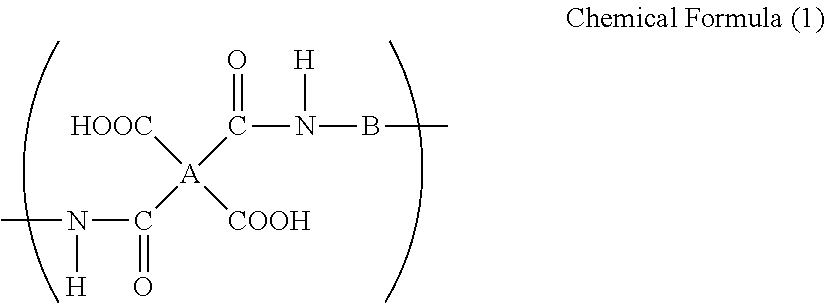
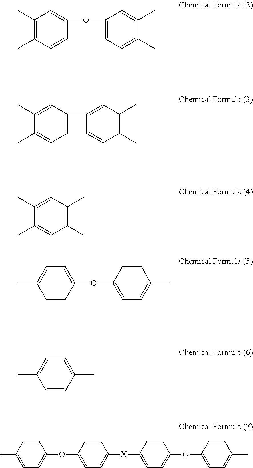
[0037]Next, the tetracarboxylic acid component and diamine component of the polyamic acid wherein A and B in the chemical formula (1) are the same as (iii) described above are described (herein below, referred to as the third polyamic acid).
[0038]Examples of the tetracarboxylic acid component which constitutes the third polyamic acid is substantially obtained by using 3,3′,4,4′-biphenyltetracarboxylic acid dianhydride or deriv

Problems solved by technology

However, when silicon, tin, or an alloy containing them, which are an active material having high charge and discharge capacity, is used, a great volume change in the active material is caused in accordance with charge and discharge.
As such, an electrode using polyfluorovinylidene or rubber-based resin as a binder resin, that have been widely used for an electrode in which carbon is used as an active material, has a problem that the active material layer is easily degraded or peeling occurs at an inter

Method used


Image

  • Binder resin composition for electrode, electrode mixture paste, and electrode
  • Binder resin composition for electrode, electrode mixture paste, and electrode
  • Binder resin composition for electrode, electrode mixture paste, and electrode

Examples


example 1

[0096]To a glass reaction vessel with internal volume of 500 mL that is equipped with a stirrer and an inlet • outlet for nitrogen gas, 400 g of NMP was added as a solvent. To the solvent, 25.85 g (0.239 mol) of PPD and 74.15 g (0.239 mol) of OPDA were added and the mixture was stirred for 10 hours at 50° C. to obtain a binder resin composition for an electrode which has a solid matter content of 18.1% by mass, solution viscosity of 4.9 Pa·s, and inherent viscosity of 0.75.

[0097]The binder resin composition for an electrode which has been obtained from the above was coated on a glass plate substrate by using a bar coater. The coated film was de-foamed and pre-dried under reduced pressure for 30 minutes at 25° C., and was then placed in a hot air dryer in nitrogen gas atmosphere under atmospheric pressure and heated for 30 minutes at 120° C., 10 minutes at 150° C., 10 minutes at 200° C., 10 minutes at 250° C., and 10 minutes at 400° C. to form a binder resin film having a thickness o...

example 2

[0100]To a glass reaction vessel with internal volume of 500 mL that is equipped with a stirrer and an inlet • outlet for nitrogen gas, 400 g of NMP was added as a solvent. To the solvent, 39.23 g (0.196 mol) of ODA and 60.77 g (0.196 mol) of OPDA were added and the mixture was stirred for 10 hours at 50° C. to obtain a binder resin composition for an electrode which has a solid matter content of 18.3% by mass, solution viscosity of 5.2 Pa·s, and inherent viscosity of 0.78.

[0101]The binder resin composition for an electrode which has been obtained from the above was coated on a glass plate substrate by using a bar coater. The coated film was de-foamed and pre-dried under reduced pressure for 30 minutes at 25° C., and was then placed in a hot air dryer in nitrogen gas atmosphere under atmospheric pressure and heated for 30 minutes at 120° C., 10 minutes at 150° C., 10 minutes at 200° C., 10 minutes at 250° C., and 10 minutes at 350° C. to form a binder resin film having a thickness o...

example 3

[0104]To a glass reaction vessel with internal volume of 500 mL that is equipped with a stirrer and an inlet • outlet for nitrogen gas, 400 g of NMP was added as a solvent. To the solvent, 56.96 g (0.139 mol) of BAPP and 43.04 g (0.139 mol) of ODPA were added and the mixture was stirred for 10 hours at 50° C. to obtain a binder resin composition for an electrode which has a solid matter content of 18.5% by mass, solution viscosity of 5.0 Pa·s, and inherent viscosity of 0.74.

[0105]The binder resin composition for an electrode which has been obtained from the above was coated on a glass plate substrate by using a bar coater. The coated film was de-foamed and pre-dried under reduced pressure for 30 minutes at 25° C., and then placed in a hot air dryer in nitrogen gas atmosphere under atmospheric pressure and heated for 30 minutes at 120° C., 10 minutes at 150° C., 10 minutes at 200° C., 10 minutes at 250° C., and 10 minutes at 350° C. to form a binder resin film having a thickness of 5...


PUM

PropertyMeasurementUnit
Temperatureaaaaaaaaaa
Fractionaaaaaaaaaa

Abstract

The present invention relates to a binder resin composition for an electrode, including a polyamic acid and a solvent, wherein the polyamic acid is (i) a polyamic acid which includes a tetracarboxylic acid component including 10 to 100 mol % of 4,4′-oxydiphthalic acid and 90 to 0 mol % of 3,3′,4,4′-biphenyltetracarboxylic acid and/or pyromellitic acid and a diamine component including an aromatic diamine having 1 to 4 aromatic rings, (ii) a polyamic acid which includes a tetracarboxylic acid component including 3,3′,4,4′-biphenyltetracarboxylic acid dianhydride and a diamine component including 10 to 90 mol % of p-phenylene diamine and 90 to 10 mol % of 4,4′-diaminodiphenyl ether, or (iii) a polyamic acid which includes a tetracarboxylic acid component including 3,3′,4,4′-biphenyltetracarboxylic acid dianhydride and a diamine component including 40 mol % or more of a bis[4-(4-aminophenoxy)phenyl] compound.

Description

TECHNICAL FIELD[0001]The present invention relates to a binder resin composition for an electrode of an electrochemical element like a lithium ion secondary battery and an electric double layer capacitor, electrode mixture paste containing the binder resin composition, and an electrode manufactured by using the electrode mixture paste.BACKGROUND ART[0002]As having high energy density and high capacity, a lithium ion secondary battery is widely used as a power supply for driving a mobile information terminal or the like. In recent days, it is also used for an industrial application like mounting in an electric • hybrid automobile or the like wherein high capacity is needed, and therefore studies to achieve even higher capacity and higher performance are carried out. One of the studies is to increase charge and discharge capacity by using silicon or tin as a negative electrode active material having a great lithium occlusion amount per unit volume, or an alloy containing them.[0003]Ho...

Claims


Application Information

Patent Timeline
IPC IPC(8): H01B1/12H01B1/24H01B1/22C08K5/3415H01G11/28H01G11/30H01G11/38
CPCH01G11/30H01G11/38H01M4/133H01M4/134H01M4/1393H01G11/28H01M4/622H01M10/0525Y02E60/122Y02E60/13H01M4/1395H01B1/22Y02E60/10H01G11/22
Inventor NAKAYAMA, TAKESHIGENAKAYAMA, TOMONORITAKABAYASHI, SEIICHIROUHIRANO, TETSUJI
Owner UBE IND LTD
Why Eureka
Try Eureka