Plane-projection multi-photon microscopy
a multi-photon microscopy and plane projection technology, applied in closed circuit television systems, instruments, television systems, etc., can solve the problems of introducing thermal mechanical damage to live tissues, and unable to achieve the effect of reducing the dwell time of live tissues
- Summary
- Abstract
- Description
- Claims
- Application Information
AI Technical Summary
Benefits of technology
Problems solved by technology
Method used
Image
Examples
example 1
Study of Axial Resolution of Technique
[0054]FIG. 4 shows the axial resolution and the sectioning images of the optical system depicted in FIG. 1. The axial resolution was determined by the full width of hall maximum (FWHM) of the axial PSF of an isolated fluorescent microspheres. In particular, the intensity profile of the brightest pixel through the sectioning of a fluorescent microsphere of diameter 1 μm was obtained and normalized by its maximum.
[0055]To obtain the axial PSF, the sample objective was moved toward the fluorescent microspheres. A stack of 120 images was acquired at a step size of 0.2 μm. For one microsphere, the maximal pixel intensity for each image was then obtained and normalized by the maximum pixel intensity of the whole stack. To compare the axial resolution, the lateral views of the sectioning image stacks were reconstructed from a conventional epifluorescence microscopy (Epi), the inventive plane-projection multi-photon microscope (PPMP), and a conventional...
example 2
Study of Optical Section of Live Tissue
[0057]To demonstrate that the inventive PPMP technique has the capability of imaging live tissue at high frame rate, optical sectioning of live, 3-D MCF-10A cell clusters was performed. These results are shown in FIG. 5, showing optical sections of live MCF-10A cells in a hemispherical structure. Fluorescence signals were from cell nuclei expressing cyan fluorescent protein-conjugated histone (H2Bcerulean) which binds to chromosomes. Exposure time of each frame is 0.2 seconds, the sample objective is 60×, with NA=1.1, n=1.33, a step size of 1 μm, and a laser average power of <10 mW. The images were then used to reconstruct the 3D view, where MCF-10A cells formed a hemispherical organization, as shown in FIG. 6. The fluorescent signals resulted from cyan fluorescent
[0058]As described above, the exposure time was set as 0.2 seconds, equivalent to 5 fps. This is the same order of the exposure time in a conventional epifluorescence microscopy (100-...
example 3
Enhanced Performance Using Customized Microlens Array
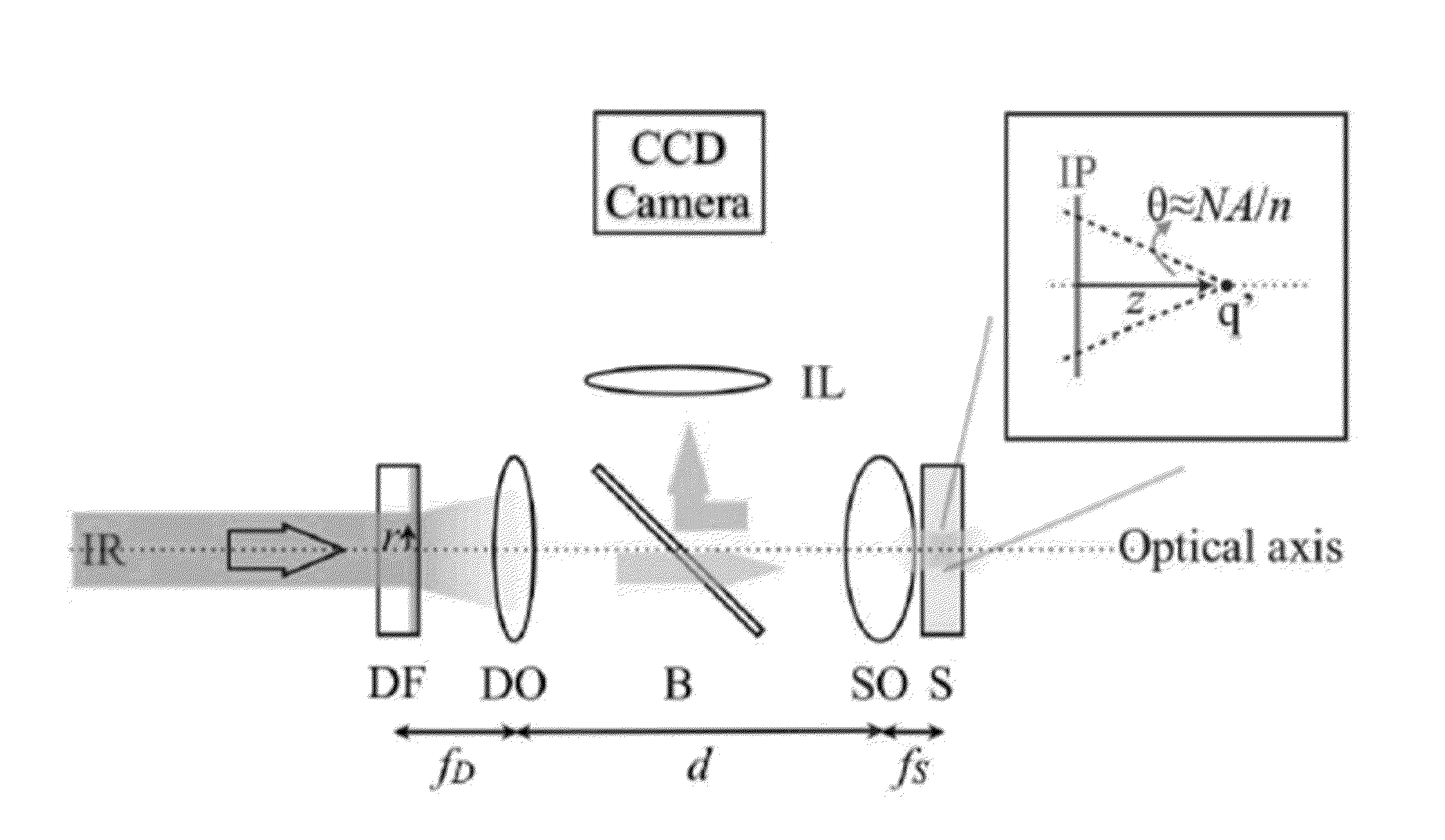
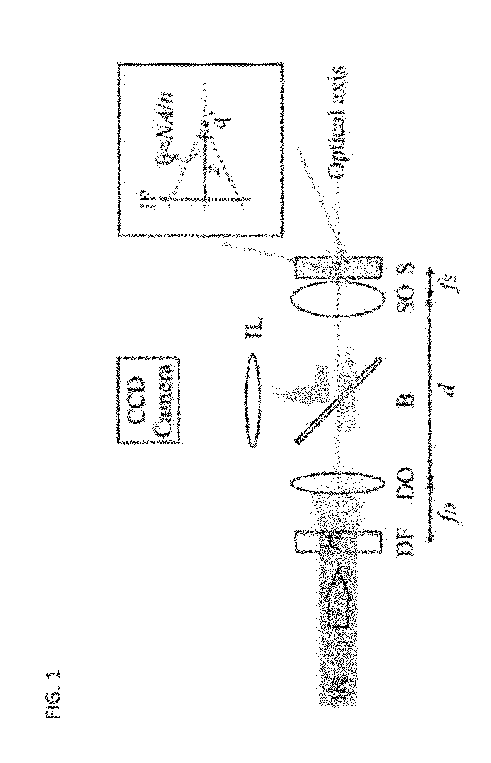
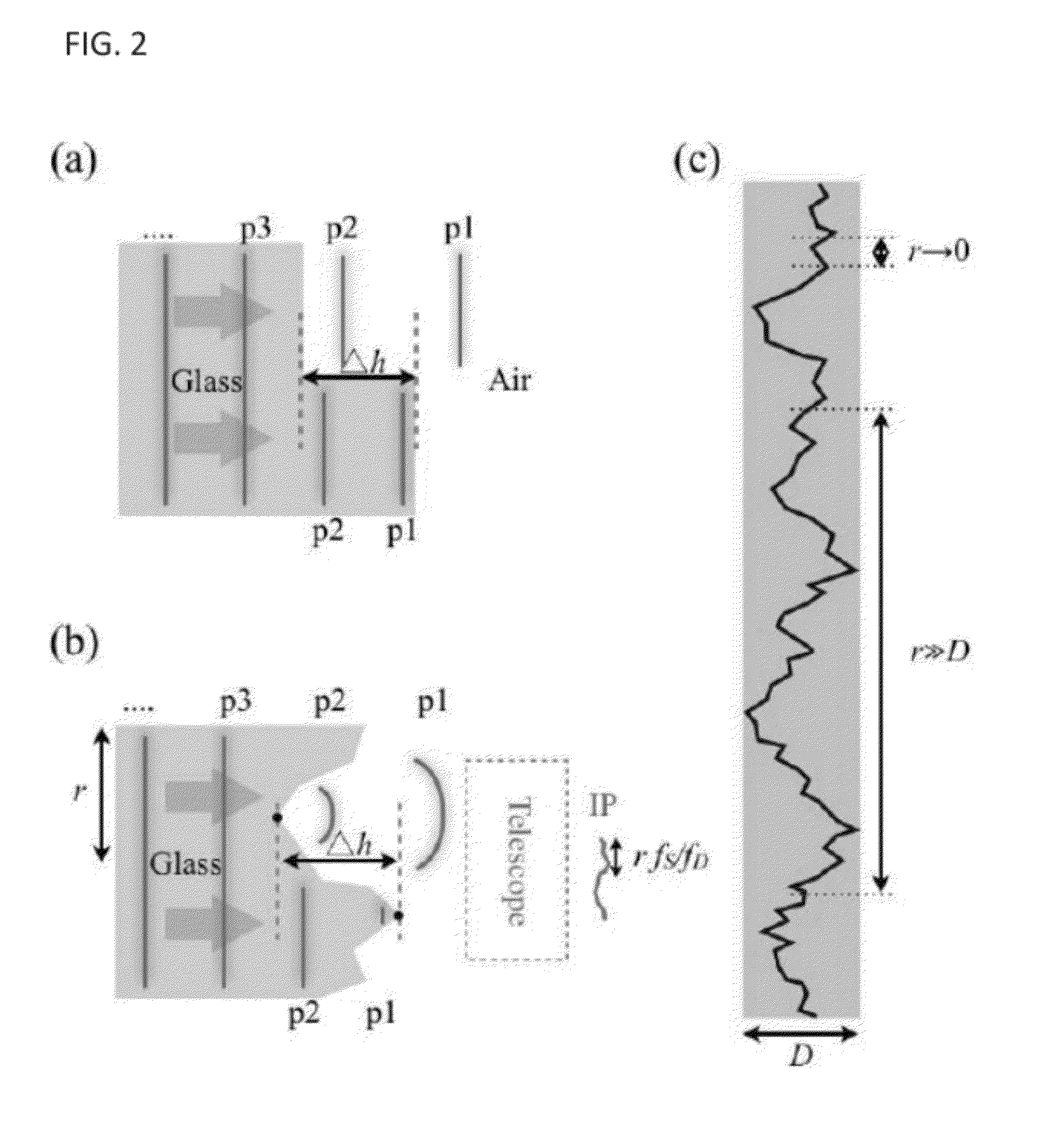
[0060]As previously described, in PPMPM optical sectioning results from the scattering of the excitation light by the varied surface geometry of the optical diffuser. The scattering creates an array of point-like light sources having random time delays with respect to each other. After re-focusing, such random time delays create a concave profile for the effective puke duration, and thus pulse width, along the optical path. (See, e.g., Yu, J.-Y. et al., Journal of Biomedical Optics, 16, 116009, (2011), the disclosure of which is incorporated herein by reference.) This profile, referred to as temporal focusing, can confine the peak excitation intensity to the image plane and hence provides optical sectioning. We note, however, that the surface geometry variation of conventional diffusers can also lead to a significant variation in the brightness of the resulting point-like light sources when imaged into the sample. This effect crea...
PUM
 Abstract
Description
Claims
Application Information
 - R&D
- Intellectual Property
- Life Sciences
- Materials
- Tech Scout
- Unparalleled Data Quality
- Higher Quality Content
- 60% Fewer Hallucinations
Browse by: Latest US Patents, China's latest patents, Technical Efficacy Thesaurus, Application Domain, Technology Topic, Popular Technical Reports.
© 2025 PatSnap. All rights reserved.Legal|Privacy policy|Modern Slavery Act Transparency Statement|Sitemap|About US| Contact US: help@patsnap.com


