Organic electroluminescence element, manufacturing method thereof, and organic electroluminescence display device

a technology of organic electroluminescence and manufacturing method, which is applied in the direction of electroluminescent light sources, organic semiconductor devices, thermoelectric devices, etc., can solve the problems of difficult material selection, low luminous efficiency, and inability to add phosphorescent materials having maximum 100% so as to reduce (i) positive holes, improve internal quantum yield rate, and improve luminous efficiency

Inactive Publication Date: 2012-09-20
SHARP KK
View PDF1 Cites 23 Cited by
  • Summary
  • Abstract
  • Description
  • Claims
  • Application Information

AI Technical Summary

Benefits of technology

[0028]According to the organic electroluminescence element of the present invention, it is possible to reduce (i) positive holes which are moved to the electron transport layer without recombining with electrons and (ii) electrons which are moved to the hole transport layer without recombining w

Problems solved by technology

However, such a phosphorescent material having maximum of 100% of internal quantum yield rate cannot be added to an organic EL element which emits blue light.
However, since the emission layer has a HOMO and a LUMO which are widely different from each other, it is difficult to employ a material, as a host material of the emission layer, (i) in which molecules conjugate and interact and (ii) which has

Method used


Image

  • Organic electroluminescence element, manufacturing method thereof, and organic electroluminescence display device
  • Organic electroluminescence element, manufacturing method thereof, and organic electroluminescence display device
  • Organic electroluminescence element, manufacturing method thereof, and organic electroluminescence display device

Examples


example 1

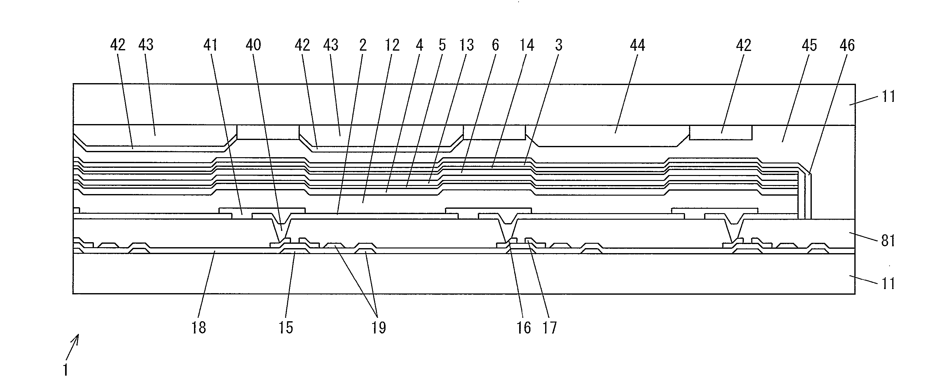
[0130]A silicon semiconductor film was deposited on a glass substrate by plasma chemical vapor deposition (plasma CVD), and was then subjected to a crystallization treatment so that a polycrystalline semiconductor film was prepared. Subsequently, the polycrystalline silicon thin film was etched so that a plurality of island-shaped patterns of polycrystalline silicon thin film are formed. Then, silicon nitride (SiN) serving as a gate insulating film was formed over the plurality of island-shaped patterns. Next, a titanium layer, an aluminum layer, and a titanium layer are stacked on the gate insulating film, in this order, so as to form stacked films (titanium-aluminum-titanium (Ti—Al—Ti)) each serving as a gate electrode, and then the stacked films were etched to be patterned. Subsequently, a source electrode and a drain electrode, each having a stacked film structure of Ti—Al—Ti, were formed on a corresponding one of the gate electrodes. A plurality of thin film transistors were th...

example 2

[0137]Note that steps, processed in Example 2 until before the step of forming an organic layer, are identical with those processed in Example 1. As such, descriptions of such steps are omitted here. The following description will therefore first discuss a step of forming a hole transport layer, and then discuss subsequent steps.

[0138]In this Example 2, a hole injection layer, having a thickness of 20 nm, was formed by depositing TAPC on anodes by the vacuum deposition method.

[0139]Then, a hole transport layer, having a thickness of 30 nm, was formed by depositing 1,3-bis(carbazole-9-yl)benzene (mCP) on the hole injection layer by the vacuum deposition method.

[0140]Subsequently, an emission layer, having a thickness of 30 nm, was formed by concurrently depositing tris(2,4,6-trimethyl-3-(pyridine-3-yl)phenyl)borane (3TPYMB) and FIr6 on the hole transport layer by the vacuum deposition method. In this case, PPT was doped with the FIr6 so that the FIr6 accounts for approximately 7.5% o...


PUM


Abstract

An organic EL element (1) of the present invention includes an emission layer (5) which is made of a host material having a highest occupied molecular orbital shallower than a highest occupied molecular orbital (8) of an organic light emitting material in the emission layer (5) (|HOMO of host material|<|HOMO of organic light emitting material|) or a host material having a lowest unoccupied molecular orbital deeper than a lowest unoccupied molecular orbital (9) of the organic light emitting material (|LUMO of host material|>|LUMO of organic light emitting material|). This makes it possible to keep the hole mobility and the electron mobility high in the host material of the emission layer (5), and therefore the hole and the electron can be efficiently transported to the emission layer (5). As a result, both the hole and the electron can be confined within the emission layer (5), and therefore the hole becomes more likely to recombine with the electron. On this account, the internal quantum yield rate can be improved, the luminous efficiency can be improved, and a driving voltage can be reduced.

Description

TECHNICAL FIELD[0001]The present invention relates to (i) an organic electroluminescence element which achieves high luminance, high efficiency, and long life duration, (ii) a method for manufacturing the organic electroluminescence element, and (iii) an organic electroluminescence display device.BACKGROUND ART[0002]In recent years, needs for thin flat panel displays (FPD) are increasing, instead of cathode-ray tube display devices which have been predominantly used conventionally. Examples of such FPDs encompass various kinds of displays such as a non-self-luminous liquid crystal display (LCD), a self-luminous plasma display panel (PDP), an inorganic electroluminescence (inorganic EL) display, and an organic electroluminescence (organic EL) display.[0003]Among those, the organic EL display has been actively studied and developed because an element (organic EL element), having various properties, is used in the organic EL display for carrying out a display. Examples of such properti...

Claims


Application Information

Patent Timeline
IPC IPC(8): H01L51/54H01L51/40
CPCH01L51/5004H01L51/5016H05B33/10H01L2251/552H01L2251/55H10K50/11H10K2101/40H10K2101/10H10K2101/00H10K2101/30
Inventor OKAMOTO
Owner SHARP KK
Why Eureka
Try Eureka