Compositions for absorbing carbon dioxide, and related processes and systems

a carbon dioxide and carbon dioxide technology, applied in the field of carbon dioxide capture processes, can solve the problems of clogging of pipelines, wider adoption of this type of technology, and sharp increases in the viscosity of liquid absorbents

Inactive Publication Date: 2013-02-28
GENERAL ELECTRIC CO
View PDF2 Cites 20 Cited by
  • Summary
  • Abstract
  • Description
  • Claims
  • Application Information

AI Technical Summary

Problems solved by technology

However, a number of deficiencies may be preventing wider adoption of this type of technology.
For example, the process can sometimes result in sharp increases in the viscosity of the liquid absorbent, which can cause clogging of pipelines.
However, the lower concentrations can greatly reduce absorbing capacity, as compared to the theoretical capacity of the neat absorbent.
Moreover, energy consumption in the MEA process can be quite high, due in large part to the need for solvent (e.g., water) heating and evaporation.
Furthermore, MEA-based absorption systems may not have the long-term thermal stability, in the presence of oxygen, in environments where regeneration temperatures typically reach at least about 120° C.
Additional drawbacks may result from the fact that the liquid absorbent which is enriched with CO2 in the MEA or hindered amine process may still contain a substantial amount of free amine and solvent (usually water).
The amine and water are usually removed in the vapor phase under thermal desorption, but can cause corrosion and other degradation in the attendant equipment.
To address this concern, specialized, corrosion-equipment materials can be used for the equipment, but this can in turn increase capital costs for the plant.
In some cases, corrosion inhibitors can be added, but the use of these specialized additives can also increase operational costs.
In addition to the corrosion problems which can result, this may decrease the available alkalinity for CO2 capture, thereby reducing process efficiency.
However, this process is often very energy-intensive, and can be economically inferior to the MEA process.
In this case, energy-intensive cooling systems are usually required for such a system, and the risks associated with unintended ammonia release may be unacceptable.
CO2 capture systems using aminosiloxane materials or other capture agents are susceptible to a number of other conflicting requirements, in terms of materials and operation.
However, as molecular weight is increased, the absorbent can dramatically increase in viscosity, especially after pick-up of the gas.
Such a phenomenon can lead to serious mass transfer limitations in a large-scale system.
However, in order to also ensure a practical, low regeneration energy level, the overall heat-of-reaction needs to be relatively low.

Method used


Image

  • Compositions for absorbing carbon dioxide, and related processes and systems
  • Compositions for absorbing carbon dioxide, and related processes and systems
  • Compositions for absorbing carbon dioxide, and related processes and systems

Examples


example 1

Synthesis of 1,3-bis(3-(2-aminoethyl)aminopropyl)-1,1,3,3-tetramethyldisiloxane (Entry 27 in Table 4, below)

[0071]Ethylenediamine (155 g, 2.58 moles) was charged to a 500 mL three-necked flask equipped with a magnetic stir bar, reflux condenser, addition funnel, and nitrogen sweep. The amine material was then heated, using an oil bath. Once the temperature reached about 95° C., 1,3-bis(3-chloropropyl)-1,1,3,3-tetramethyldisiloxane (73 g, 254 mmols) was added drop-wise over about 2 hours. During this time. the temperature of the oil bath was allowed to increase to about 110-115° C. Once addition was complete, the reaction mixture was allowed to continue at this temperature for 2 more hours, at which time proton NMR readings indicated that the reaction was complete.

[0072]The mixture was then cooled, and some of the excess ethylene diamine was stripped off. At this point, the material was cooled to room temperature, and partitioned between chloroform and 10% NaOH. The organic phase was...

example 2

Synthesis of tris(3-aminopropyldimethylsiloxy)-3-aminopropylsilane (M′3T′) (Entry 29 in Table 4, below)

[0073]42.1 g of GAP-0 (0.339 mols M′) was mixed with 25.0 g 3-aminopropyltriethoxysilane (0.113 mols), and 0.65 g of tetramethylammonium hydroxidepentahydrate. The solution was heated at 60° C. (under N2) for an hour, and then 6.8 mL of water were added. Heating was then continued up to 90-95° C. 70 mL toluene was added, and after another hour a vacuum was applied and the toluene as well as water, and ethanol were stripped off. Once solvent stripping was complete, NMR showed the ethoxy groups to be essentially gone. Heating was continued overnight to ensure the reaction was at equilibrium. Then, the mixture was further heated and stripped as above (i.e. house vacuum, strip up to 165° C.). On cooling to room temperature, 53.8 g of material (98.5% yield) was obtained as a light yellow oil. 1H NMR (CDCl3) d 2.60 (t, J=6, 8H, CH2NH2), 1.39 (m, 8H, CH2CH2CH2), 1.04 (br. s., 8H, NH2), 0....

example 3

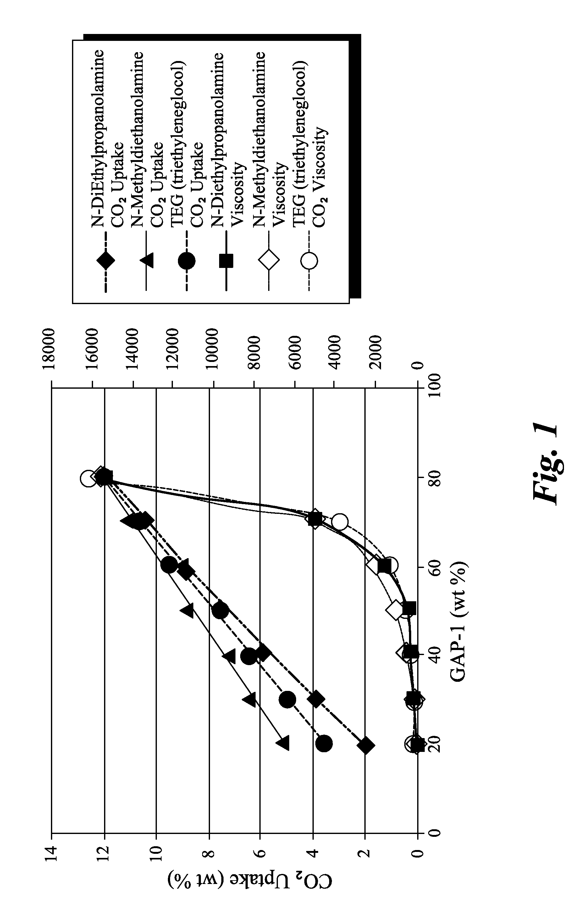
Synthesis of 1,5-bis(3-aminopropyl)-1,1,3,3,5,5-hexamethyltrisiloxane (sometimes referred to as “GAP-1”, entry 25 in Table 4, below)

[0074]20.0 g of GAP-0 (0.0805 mols) was mixed with 6.0 g D4 (0.0805 mols D) and 0.15 g of tetramethyl-ammoniumhydroxide pentahydrate. The mixture was heated to ca. 40° C. under vacuum for an hour to remove some of the water from the catalyst. Next, a nitrogen atmosphere was established, and the temperature was increased to 90-95° C., and allowed to react overnight. The reaction mixture was then heated to 150° C. for 30 minutes. A vacuum was then carefully applied (house vacuum). Heating was then continued to 165° C., and the most volatiles species were stripped off. After cooling, ca. 25 g of product (96% yield) was obtained as a light yellow oil. 1H NMR (CDCl3) d 2.60 (t, J=6, 4H, CH2NH2), 1.39 (m, 4H, CH2CH2CH2), 1.03 (br. s., 4H, NH2), 0.45 (m, 4H, CH2Si), 0.05 to −0.06 (m, 18.6H, CH3Si).


PUM

PropertyMeasurementUnit
boiling pointaaaaaaaaaa
viscosityaaaaaaaaaa
temperatureaaaaaaaaaa

Abstract

A carbon dioxide absorbent is disclosed. The absorbent compostion contains a liquid, non-aqueous, silicon-based material, functionalized with one or more groups that reversibly react with CO2 and/or have a high-affinity for CO2; and at least one amino alcohol compound. A method for reducing the amount of carbon dioxide in a process stream is also described. The method includes the step of contacting the stream with the carbon dioxide absorbent composition. A power plant that includes a carbon dioxide removal unit based on the carbon dioxide absorbent is also described.

Description

[0001]The present application claims the benefit, under 35 U.S.C. 120, of pending application Ser. No. 12 / 512,105 (Robert J. Perry et al;), filed on Jul. 30, 2009; and Ser. No. 12 / 512,577 (Robert J. Perry et al), filed Jul. 30, 2009. The contents of each of these pending applications are incorporated by reference herein.BACKGROUND[0002]This invention generally relates to processes for capturing carbon dioxide (CO2) from gas streams.[0003]The emission of carbon dioxide into the atmosphere from industrial sources such as power plants is now considered to be a principal cause of the “greenhouse effect”, which contributes to global warming. In response, tremendous efforts are underway to reduce emissions of CO2. Many different processes have been developed to attempt to accomplish this task. Examples include polymer and inorganic membrane permeation; removal of CO2 by adsorbents such as molecular sieves; cryogenic separation; and scrubbing with a solvent that is chemically reactive with...

Claims


Application Information

Patent Timeline
Patent Type & Authority Applications(United States)
IPC IPC(8): B01D53/62C09K3/00
CPCY02C10/06Y02C10/04B01D53/1475B01D53/1493B01D53/62B01D2252/20426B01D2258/0283B01D2252/20484B01D2252/20489B01D2252/205B01D2252/40B01D2252/504B01D2257/504B01D2252/20431Y02A50/20Y02C20/40
Inventor DAVIS, JASON LOUISPERRY, ROBERT JAMES
Owner GENERAL ELECTRIC CO
Why Eureka
Try Eureka