Metal complex dye, photoelectric conversion element and dye-sensitized solar cell

a solar cell and photoelectric conversion technology, applied in the field of metal complex dyes, photoelectric conversion elements and dye-sensitized solar cells, can solve the problems of long energy payback time, low conversion efficiency of solar cells that have been applied so far, and poor durability in many cases, so as to achieve good photoelectric conversion characteristics and reduce the effect of conversion efficiency and excellent photoelectric conversion characteristics

Inactive Publication Date: 2013-04-11
FUJIFILM CORP
View PDF0 Cites 16 Cited by
  • Summary
  • Abstract
  • Description
  • Claims
  • Application Information

AI Technical Summary

Benefits of technology

[0017]According to the present invention, it is possible to provide a metal complex dye that is excellent in photoelectric conversion characteristics such as conversion efficiency, and durability with a small decrease in the photoelectric conversion characteristics even after use over a long period of time; a photoelectric conversion element prepared by using the same as a sensitizing dye; and a dye-sensitized solar cell composed of such a photoelectric conversion element.
[0018]Other and further features and advantages of the invention will appear more fully from the following description, appropriately referring to the accompanying drawing.

Problems solved by technology

However, in order to widely expand use of these solar cells to an application such as a household power supply, these solar cells have problems such as difficulty in manufacturing the cells at a low cost or securing a raw material, and also a long energy payback time.
However, the solar cells that have been applied so far have generally had a low conversion efficiency and a poor durability in many cases.
However, a decrease in conversion efficiency after use is large, and the cell has a problem of durability.
However, even the photoelectric conversion element described in Patent Literature 3 is not satisfactory in view of durability.
However, the photoelectric conversion element is not satisfactory even with the initial conversion efficiency and durability of J2.

Method used


Image

  • Metal complex dye, photoelectric conversion element and dye-sensitized solar cell
  • Metal complex dye, photoelectric conversion element and dye-sensitized solar cell
  • Metal complex dye, photoelectric conversion element and dye-sensitized solar cell

Examples


examples

Preparation of Exemplified Dyes

(Preparation of Exemplified Compound D-1-1a)

[0129]The exemplified dye D-1-1a was prepared according to the method shown in the following scheme.

(i) Preparation of Compound d-1-2

[0130]To 70 mL of triethylamine and 50 mL of tetrahydrofuran, 25 g of Compound d-1-1, 33.8 g of Pd(dba), 8.6 g of triphenyl phosphine, 2.5 g of copper iodide, and 25.2 g of 1-heptyne were added. The resultant mixture was stirred at room temperature, and stirred at 80° C. for 4.5 hours. After concentration, purification was performed by means of column chromatography, and thus 26.4 g of Compound d-1-2 was obtained.

(ii) Preparation of Compound d-1-4

[0131]Under a nitrogen atmosphere at −15° C., 6.7 g of Compound d-1-3 was dissolved in 200 mL of THF (terahydrofuran), and LDA (lithium diisopropylamide) that was separately prepared was added dropwise in an amount of 2.5 equivalents of Compound d-1-3, and the resultant mixture was stirred for 75 minutes. Then, a solution in which 15 g ...

experiment 1

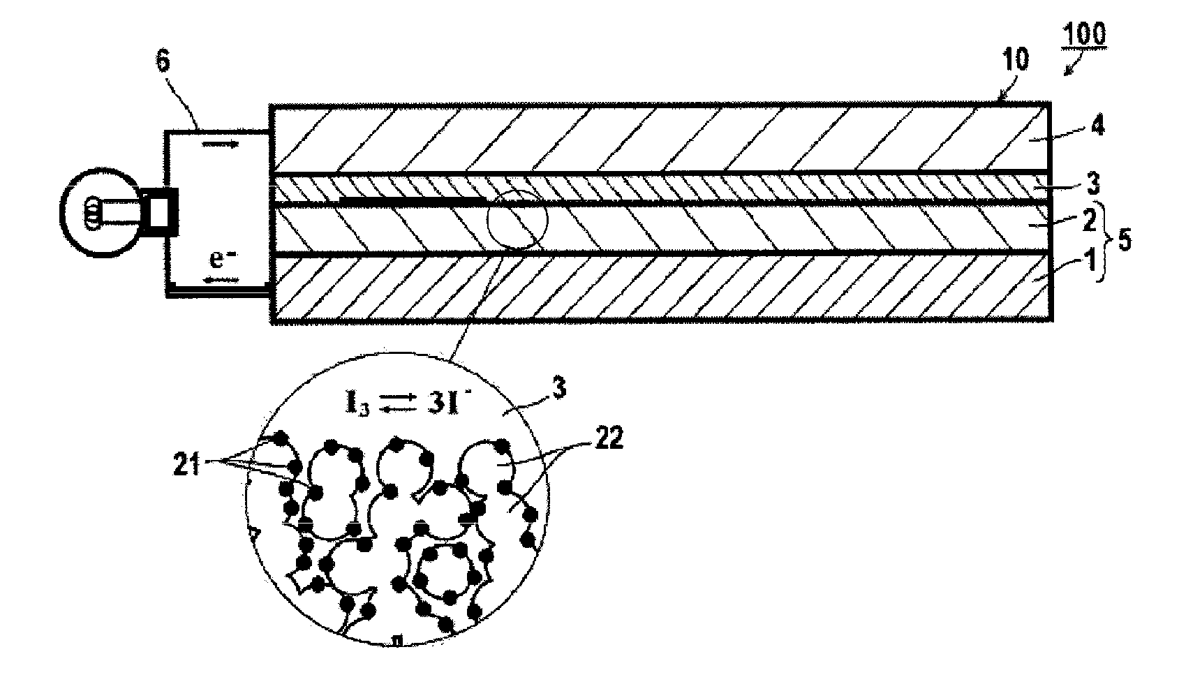
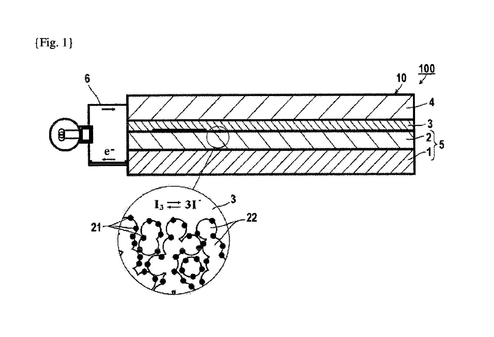
Production of Photoelectric Conversion Element

[0184]On a glass substrate, a film of tin oxide doped with fluorine was formed by sputtering as a transparent conductive film, and this film was scribed with a laser to partition the transparent conductive film into two parts. Anatase type titanium oxide particles (average particle size: 50 nm) were sintered on one part of the electrically conductive films, and thus a light-receiving electrode was prepared. Thereafter, a dispersion liquid containing silica particles and rutile type titanium oxide at a ratio of 40:60 (mass ratio) was prepared, and this dispersion liquid was applied on the light-receiving electrode described above and sintered. Thus, an insulating porous body was formed. Subsequently, a carbon electrode was formed as a counter electrode.

[0185]Next, the glass substrate having the insulating porous body formed thereon was immersed for 48 hours in an ethanol solution of each of the sensitizing dyes indicated in the following ...

experiment 2

1. Preparation of Raw Material Compound Solution for ITO Film

[0190]Were dissolved 5.58 g of indium(III) chloride tetrahydrate and 0.23 g of tin(II) chloride dihydrate in 100 mL of ethanol, and thus a raw material compound solution for ITO film was prepared.

2. Preparation of Raw Material Compound Solution for FTO Film

[0191]Was dissolved 0.701 g of tin(IV) chloride pentahydrate in 10 mL of ethanol, and 0.592 g of a saturated aqueous solution of ammonium fluoride was added thereto. This mixture was completely dissolved in an ultrasonic bath over about 20 minutes, and thus a raw material compound solution for FTO film was prepared.

[0192]Then, the surface of a heat resistant glass plate having a thickness of 2 mm was subjected to chemical cleaning and was dried. Subsequently, this glass plate was placed in a reactor and was heated with a heater. When the heating temperature of the heater reached 450° C., the raw material compound solution for ITO film obtained was sprayed over the glass ...


PUM

PropertyMeasurementUnit
absorption wavelengthaaaaaaaaaa
semiconductoraaaaaaaaaa
electrically conductiveaaaaaaaaaa

Abstract

A metal complex dye, containing a ligand LL1 having a structure represented by Formula (I):
wherein R1 and R2 represent a specific substituent; L1 and L2 represent a group composed of at least one kind of group selected from the group consisting of an ethenylene group, an ethynylene group and an arylene group, and conjugate with R1 or R2, and the bipyridine; the ethenylene group and the arylene group may be substituted or unsubstituted; R3 and R4 represent a substituent; n1 and n2 represent an integer of 0 to 3; A1 and A2 represent an acidic group or a salt thereof; and n3 and n4 represent an integer of 0 to 3.

Description

TECHNICAL FIELD[0001]The present invention relates to a metal complex dye that is excellent in durability and photoelectric conversion characteristics, a photoelectric conversion element containing semiconductor fine particles prepared by using the same as a sensitizing dye, and a dye-sensitized solar cell using such a photoelectric conversion element.BACKGROUND ART[0002]As a solar cell used for photovoltaic power generation, a solar cell composed of single crystal silicon, polycrystal silicon, amorphous silicon, or a compound such as cadmium telluride or copper indium selenide is a main research and development target, and part thereof is put in practical use. However, in order to widely expand use of these solar cells to an application such as a household power supply, these solar cells have problems such as difficulty in manufacturing the cells at a low cost or securing a raw material, and also a long energy payback time. These problems are required to be overcome. Meanwhile, man...

Claims


Application Information

Patent Timeline
Patent Type & Authority Applications(United States)
IPC IPC(8): C07F15/00H01L51/42
CPCC07D213/79Y02E10/549C07D409/10C07D409/14C07D519/00C07F15/0026C07F15/0053C09B23/0075C09B23/105C09B23/107C09B57/10H01G9/2031H01G9/2059H01G9/2063H01G9/2068H01L51/0064H01L51/0086H01M14/005Y02E10/542H01L51/4213C09B57/007C07D409/06H10K85/652H10K85/344H01L31/04H01M14/00H10K30/10
Inventor TANI, YUKIOSUSUKI, TATSUYAKOBAYASHI, KATSUMIKIMURA, KEIZO
Owner FUJIFILM CORP
Why Eureka
Try Eureka