Electronic Device Module Comprising Film of Homogeneous Polyolefin Copolymer and Grafted Silane

a technology of homogenous polyolefin and electrolyte, which is applied in the direction of basic electric elements, layered products, chemical instruments and processes, etc., can solve the problems of less than ideal pv cell encapsulating film material, greater than 30% loss in power output of solar modules, and eva resins that absorb moisture and other issues, to achieve the effect of good adhesion to glass, faster production rate, and higher processing temperatur

Inactive Publication Date: 2013-09-12
NAUMOVITZ JOHN A +3
View PDF2 Cites 15 Cited by
  • Summary
  • Abstract
  • Description
  • Claims
  • Application Information

AI Technical Summary

Benefits of technology

[0025]In another embodiment, the invention is the electronic device module as described in the two embodiments above except that the polymeric material in intimate contact with at least one surface of the electronic device is a co-extruded material in which at least one outer skin layer (i) does not contain peroxide for crosslinking, and (ii) is the surface which comes into intimate contact with the module. Typically, this outer skin layer exhibits good adhesion to glass. This outer skin of the co-extruded material can comprise any one of a number of different polymers, but is typically the same polymer as the polymer of the peroxide-containing layer but without the peroxide. This embodiment of the invention allows for the use of higher processing temperatures which, in turn, allows for faster production rates without unwanted gel formation in the encapsulating polymer due to extended contact with the metal surfaces of the processing equipment. In another embodiment, the extruded product comprises at least three layers in which the skin layer in contact with the electronic module is without peroxide, and the peroxide-containing layer is a core layer.

Problems solved by technology

No one polymeric material delivers maximum performance on all of these properties in any particular application, and usually trade-offs are made to maximize the performance of properties most important to a particular application, e.g., transparency and protection against the environment, at the expense of properties secondary in importance to the application, e.g., cure time and cost.
EVA resins are typically stabilized with ultra-violet (UV) light additives, and they are typically crosslinked during the solar cell lamination process using peroxides to improve heat and creep resistance to a temperature between about 80 and 90° C. However, EVA resins are less than ideal PV cell encapsulating film material for several reasons.
This discoloration can result in a greater than 30% loss in power output of the solar module after as little as four years of exposure to the environment.
EVA resins also absorb moisture and are subject to decomposition.
One of the most fundamental limitations on the efficiency of a solar cell is the band gap of its semi-conducting material, i.e., the energy required to boost an electron from the bound valence band into the mobile conduction band.
Photons with energy higher than the band gap are absorbed, but their excess energy is wasted (dissipated as heat).
Crosslinking, particularly chemical crosslinking, while addressing one problem, e.g., thermal creep, can create other problems.
While this addresses the thermal creep problem, it creates a corrosion problem, i.e., total crosslinking is seldom, if ever, fully achieved and this leaves residual peroxide in the EVA.
Another potential problem with peroxide-initiated cros slinking is the buildup of crosslinked material on the metal surfaces of the process equipment.
Over longer periods of extrusion time, crosslinked material can form at the metal surfaces and require cleaning of the equipment.
The current practice to minimize gel formation, i.e., this crosslinking of polymer on the metal surfaces of the processing equipment, is to use low processing temperatures which, in turn, reduces the production rate of the extruded product.
This thermoplasticity, however, must not be obtained at the expense of effective thermal creep resistance.

Method used


Image

  • Electronic Device Module Comprising Film of Homogeneous Polyolefin Copolymer and Grafted Silane
  • Electronic Device Module Comprising Film of Homogeneous Polyolefin Copolymer and Grafted Silane
  • Electronic Device Module Comprising Film of Homogeneous Polyolefin Copolymer and Grafted Silane

Examples


examples

[0162]All raw materials (ethylene, 1-octene) and the process solvent (a narrow boiling range high-purity isoparaffinic solvent trademarked Isopar E and commercially available from Exxon Mobil Corporation) are purified with molecular sieves before introduction into the reaction environment. Hydrogen is supplied in pressurized cylinders as a high purity grade and is not further purified. The reactor monomer feed (ethylene) stream is pressurized via mechanical compressor to above reaction pressure at 525 psig. The solvent and comonomer (1-octene) feed is pressurized via mechanical positive displacement pump to above reaction pressure at 525 psig. The individual catalyst components are manually batch diluted to specified component concentrations with purified solvent (Isopar E) and pressured to above reaction pressure at 525 psig. All reaction feed flows are measured with mass flow meters and independently controlled with computer automated valve control systems.

[0163]The continuous sol...

specific embodiments

[0169]The following prophetic examples 5 and 6 further illustrate the invention. Unless otherwise indicated, all parts and percentages are by weight.

example 5

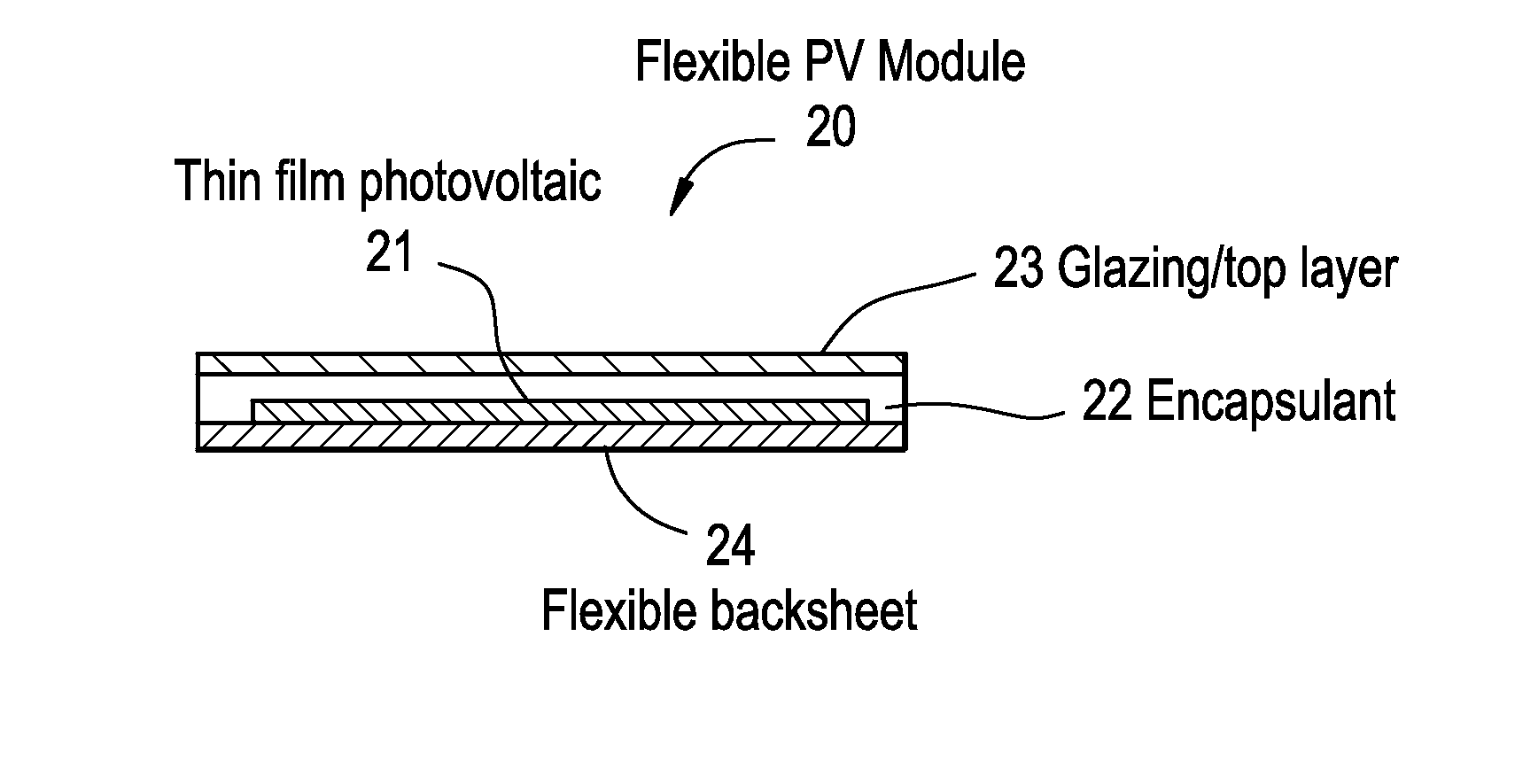
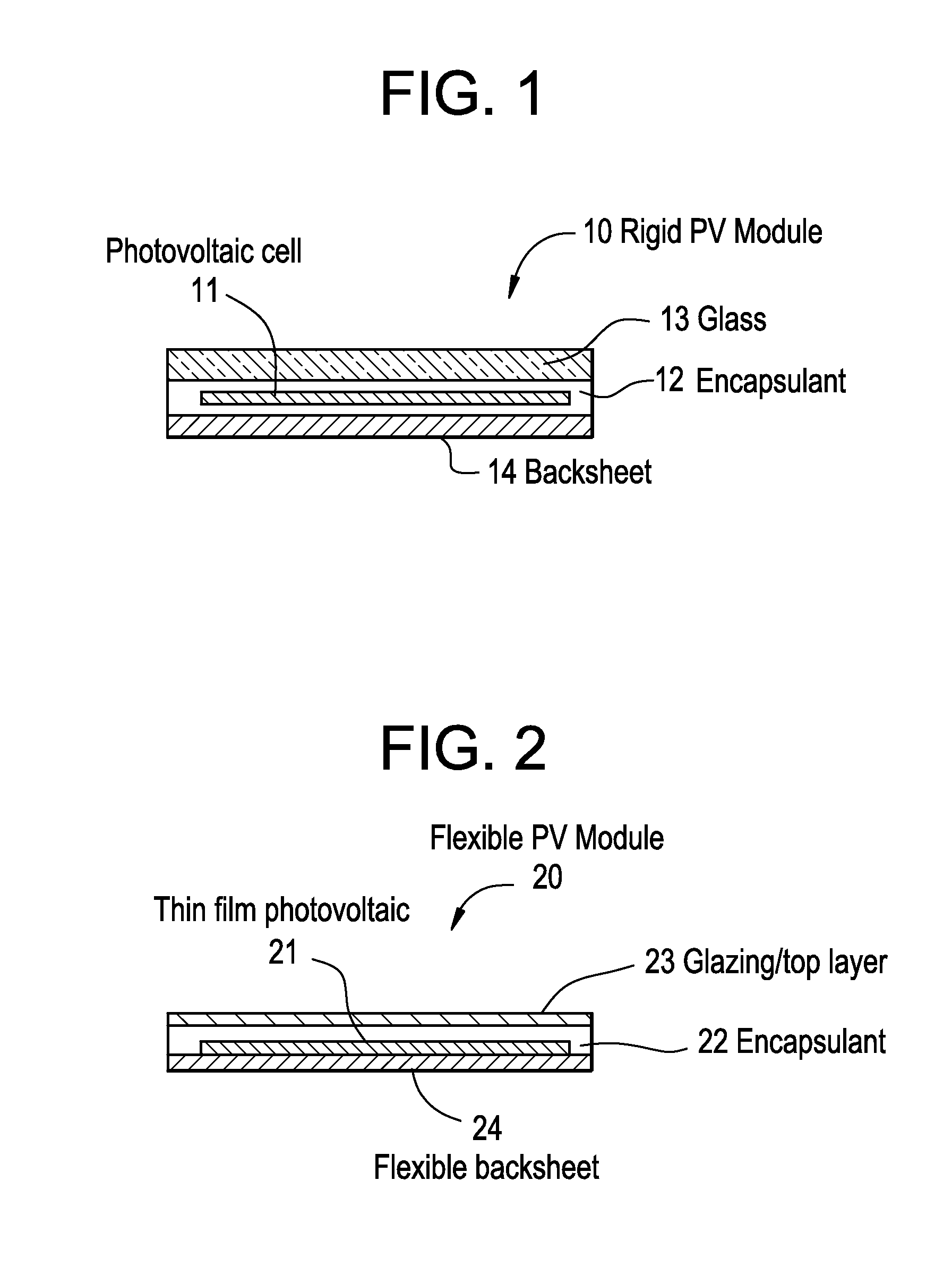
[0170]A monolayer 15 mil thick protective film is made from a composition comprising 97 wt % of Sample 1, 3 wt % of vinyl silane, 1.5 wt % of Lupersol® 101, 0.8 wt % of tri-allyl cyanurate, 0.1 wt % of Chimassorb® 944, 0.2 wt % of Naugard® P, and 0.3 wt % of Cyasorb® UV 531. The melt temperature during film formation is kept below about 120° C. to avoid premature crosslinking of the film during extrusion. This film is then used to prepare a solar cell module. One film layer is laminated at a temperature of about 150° C. to a superstrate, e.g., a glass cover sheet, and the front surface of a solar cell, and a second layer then to the back surface of the solar cell and a backskin material, e.g., another glass cover sheet or any other substrate. The protective film is then subjected to conditions that will ensure that the film is substantially crosslinked.

Formulations and Processing Procedures:

[0171]Step 1: Use ZSK-30 extruder with Adhere Screw to compound resin and additive package.

[0...


PUM

PropertyMeasurementUnit
densityaaaaaaaaaa
temperatureaaaaaaaaaa

Abstract

An electronic device module comprising:
    • A. At least one electronic device, e.g., a solar cell, and
    • B. A polymeric material in intimate contact with at least one surface of the electronic device, the polymeric material comprising (1) an ethylene interpolymer comprising an overall polymer density of not more than 0.905 g/cm3; total unsaturation of not more than 125 per 100,000 carbons; up to 3 long chain branches/1000 carbons; vinyl-3 content of less than 5 per 100,000 carbons; and a total number of vinyl groups/1000 carbons of less than the quantity (8000/Mn), wherein the vinyl-3 content and vinyl group measurements are measured by gel permeation chromatography (145° C.) and 1H-NMR (125° C.), (2) grafted vinyl silane, (3) optionally, free radical initiator or a photoinitiator in an amount of at least about 0.05 wt % based on the weight of the copolymer, and (3) optionally, a co-agent in an amount of at least about 0.05 wt % based upon the weight of the copolymer.

Description

CROSS REFERENCE TO RELATED APPLICATION[0001]This application claims priority from U.S. provisional application Ser. No. 61 / 351,577, filed Jun. 4, 2010, which is incorporated herein by reference in its entirety. This application is related to U.S. National application Ser. No. 11 / 857,208 filed Sep. 18, 2007, which claims the benefit of U.S. Ser. No. 60 / 826,328 filed Sep. 20, 2006; and U.S. Ser. No. 60 / 865,965 filed Nov. 15, 2006; the disclosures of which are incorporated herein by reference for U.S. prosecution purposes.FIELD OF THE INVENTION[0002]This invention relates to electronic device modules. In one aspect, the invention relates to electronic device modules comprising an electronic device, e.g., a solar or photovoltaic (PV) cell, and a protective polymeric material while in another aspect, the invention relates to electronic device modules in which the protective polymeric material is a polymeric material in intimate contact with at least one surface of the electronic device, ...

Claims


Application Information

Patent Timeline
Patent Type & Authority Applications(United States)
IPC IPC(8): H01L31/0203H01L23/29
CPCB32B17/10018B32B17/1055C08F210/16C08L23/08H01L2924/0002H01L31/048Y02E10/50H01L23/293H01L31/0203C08L2666/24C08F210/14C08F2500/02C08F2500/09C08F2500/11C08F2500/26H01L2924/00C08F255/02H01L31/0481C08F230/085
Inventor NAUMOVITZ, JOHN A.PATEL, RAJEN M.WU, SHAOFUNEIMANN, DEBRA H.
Owner NAUMOVITZ JOHN A
Why Eureka
Try Eureka