Self-assembly of small structures

a self-assembly and structure technology, applied in the field of structure formation, can solve the problems of high complexity of the mechanism driving dynamic templating, and achieve the effects of reducing the area of the structure, enhancing the agglomeration process, and facilitating the fabrication of dynamic template widths

Active Publication Date: 2013-10-17
TEMPLE UNIVERSITY
View PDF0 Cites 33 Cited by
  • Summary
  • Abstract
  • Description
  • Claims
  • Application Information

AI Technical Summary

Benefits of technology

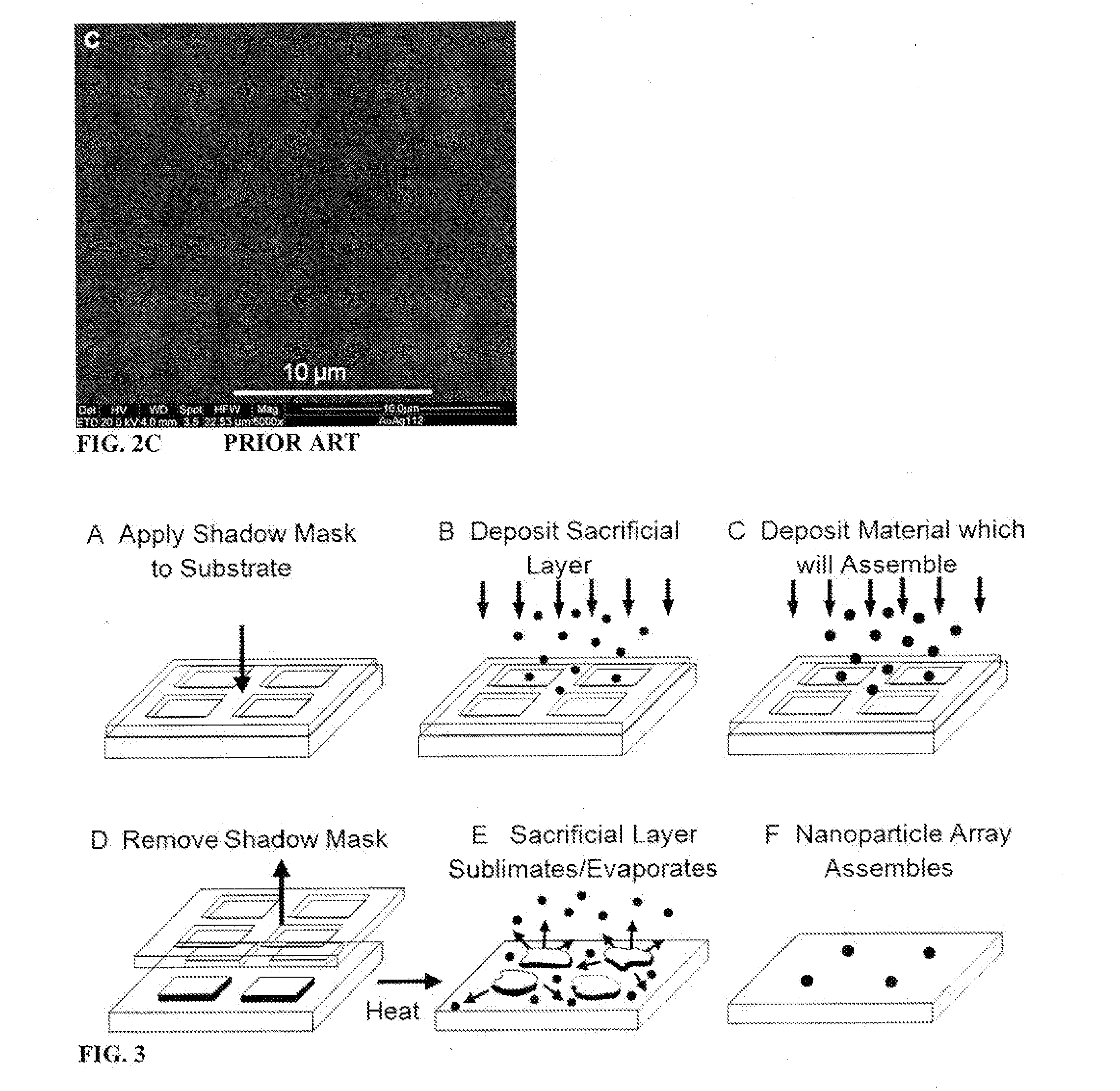
[0056]Embodiments of the present invention make possible the precise fabrication of particles and other structures in the sub-micrometer to nanometer scale by first forming a structure in the size scale reasonably achievable by templating or other available techniques, and then reducing the area of the structure in a relatively controlled manner. Control that in conventional dewetting is lost as the dewettable layer becomes too thin can be regained through the formation of a much thicker 2-component structure where one component slowly sublimes, evaporates, or otherwise vaporizes. In this scenario, as the larger structure becomes progressively smaller, a second, more stable, component experiences a forced migration to progressively smaller length-scales. The end product, once the entire first component has sublimed or evaporated, can be a single particle of nanometer-scale dimensions.
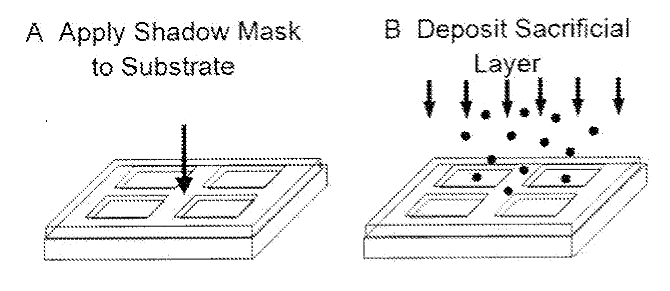
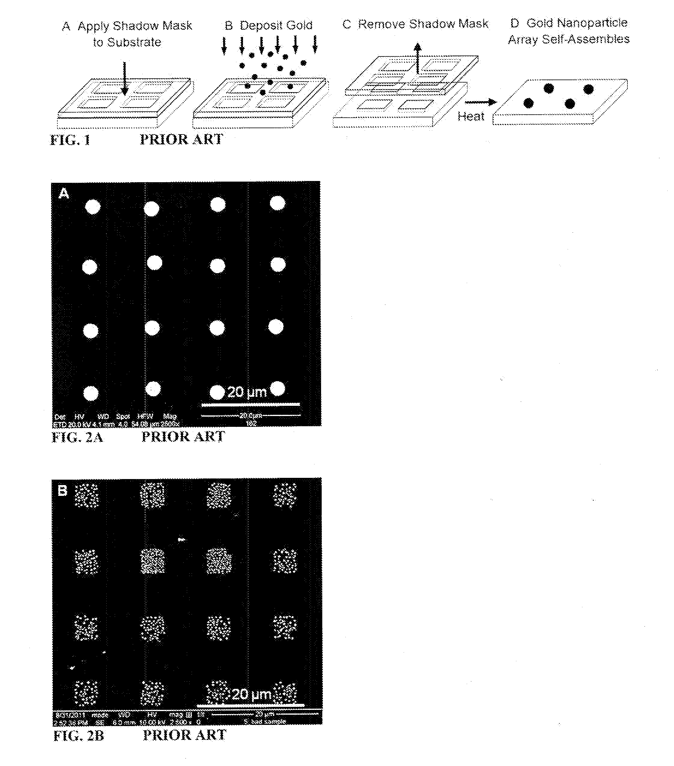
[0057]Embodiments of the present invention can overcome or greatly mitigate the previous limitations of templated dewetting, through a processing route that can see orders of magnitude enhancements to the agglomeration process. The net effect of these enhancements allows atoms scattered more thinly over a much larger area to agglomerate into a single substrate supported structure. Embodiments of the devised fabrication route use one or more intermediate layers deposited between the substrate and agglomerating film as a sacrificial layer(s). This sacrificial layer forms a pedestal upon which the dewetting occurs. The pedestal material is chosen such that it sublimes (or evaporates) away from its sides creating a progressively smaller area on the top of the pedestal that can support the agglomerating film. This reduction in area results in a forced migration of the agglomerating atoms to the center of the pedestal. Eventually, the pedestal is completely annihilated leaving the agglomerated structure on the underlying substrate. A simple analogy to this process is one where a shrinking island will force its i...

Problems solved by technology

The mechanisms driving dynamic templating are highly complex, involving a layered structure which emits material, intermixes, evolves from mic...

Method used


Image

  • Self-assembly of small structures
  • Self-assembly of small structures
  • Self-assembly of small structures

Examples


example 1

Gold on (0001)-Oriented Sapphire using Antimony Pedestal

[0195]A sapphire substrate with a (0001)-orientation, obtained from a commercial vendor (MTI Corporation), was cut to size (8 mm×8 mm×0.5 mm) and then cleaned in an ultrasonic bath using common solvents (methanol, acetone, isopropanol). A shadow mask was mechanically clamped over the substrate surface and then mounted onto the sample holder assembly in a pulsed laser deposition (PLD) chamber (Neocera Pioneer 120). The shadow mask consisted of an electroformed nickel mesh (Precision Eforming) with 5 μm×5 μm square openings and a repeat spacing of 12.5 μm. The exposed mesh area had a diameter of 5 mm. The deposition chamber was then evacuated to a base pressure of 10−7 torr. Mounted on the target carousel of the deposition chamber were 1″ (25 mm) diameter targets of antimony (Kurt J. Lesker) and gold (Alfa Aesar). Antimony was first deposited through the mask using PLD.

[0196]Pulses from an excimer laser (Lambda Physik Compex 102 ...

example 2

Silver on (0001)-Oriented Sapphire using Bismuth Pedestal

[0197]The procedure was the same as Example 1, except as follows. The targets mounted on the target carousel of the deposition chamber were 1″ diameter targets of bismuth and silver (Alfa Aesar). Bismuth was first deposited. A pedestal height of 480 nm was obtained using 7500 laser pulses. This deposition was immediately followed by a silver deposition of 0.36 nm obtained using 100 laser pulses. The tube furnace temperature was ramped to 750° C. in 13 min where it was held for 10 min after which the furnace was turned off and allowed to cool to room temperature. The array of sub-micrometer silver structures shown in FIG. 5 was formed.

example 3

Two-Layer Template

[0198]The procedure was the same as Example 1, except as follows. The targets mounted on the target carousel of the deposition chamber were 1″ diameter targets of antimony (Kurt J. Lesker), gold (Alfa Aesar) and silver (Alfa Aesar). The substrate used was (100) MgAl2O4. The pedestal consisted of 300 nm of antimony topped with 4 nm of silver. This deposition was immediately followed by a gold deposition of 3 laser pulses using a laser power of 1.5 J / cm2. When the mask was removed, a sub-monolayer of gold was left on the surface of each silver / antimony pedestal. The tube furnace temperature was ramped to 600° C. in 9 minutes where it was held for 30 min. The temperature was then ramped to 900° C. in 11 min to sublime the silver, after which the furnace was turned off and the sample was allowed to cool to room temperature. The array of nanometer-scale gold structures shown in FIG. 6a was formed. Because of the very small size of the nanoparticles, and the very small q...


PUM


Abstract

Small structures are formed by applying to a substrate a structural material and a layer of a sacrificial material having a lower surface energy than the structural material, to form an intermediate product. The substrate is then heated to a temperature at which the sacrificial material evaporates or sublimes and the structural material is mobilized. The sacrificial material is permitted to evaporate or sublime, an area of the substrate covered by the sacrificial material to diminish, and the structural material to agglomerate on the remaining sacrificial material to form a structure.

Description

BACKGROUND OF THE INVENTION[0001]The invention relates to the formation of structures, and especially to the formation of sub-micrometer-scale or nanometer-scale structures by forming a layer of material and then concentrating that layer into a smaller area. The invention also relates to the self-assembly of sub-micrometer and nanometer length-scale substrate-based structures. The “structures” formed may be as simple as round, usually hemispherical or near hemispherical, micro- or nanoparticles on a substrate. They may also be highly faceted.[0002]The rapid advances in solid state electronics over the last forty years are founded on the fabrication of wafer-based materials and interfaces with well-defined properties situated at well-defined locations where, over time, the density of structures has steadily increased as their dimensions have steadily decreased. This triumph of science and engineering is now being challenged by nanometer length-scales and quantum confinement effects. ...

Claims


Application Information

Patent Timeline
IPC IPC(8): B05D1/32
CPCB05D1/32B82B3/0014B81C1/00031B82Y10/00B82Y30/00B82Y40/00H01L29/66439H01L29/66469H01L29/0676H01L29/1606Y10T428/24942
Inventor NERETINA, SVETLANAHUGHES, ROBERT ALANFARZINPOUR, POUYAN
Owner TEMPLE UNIVERSITY
Why Eureka
Try Eureka