

Patterning process
- Summary
- Abstract
- Description
- Claims
- Application Information
AI Technical Summary
Benefits of technology
Problems solved by technology
Method used
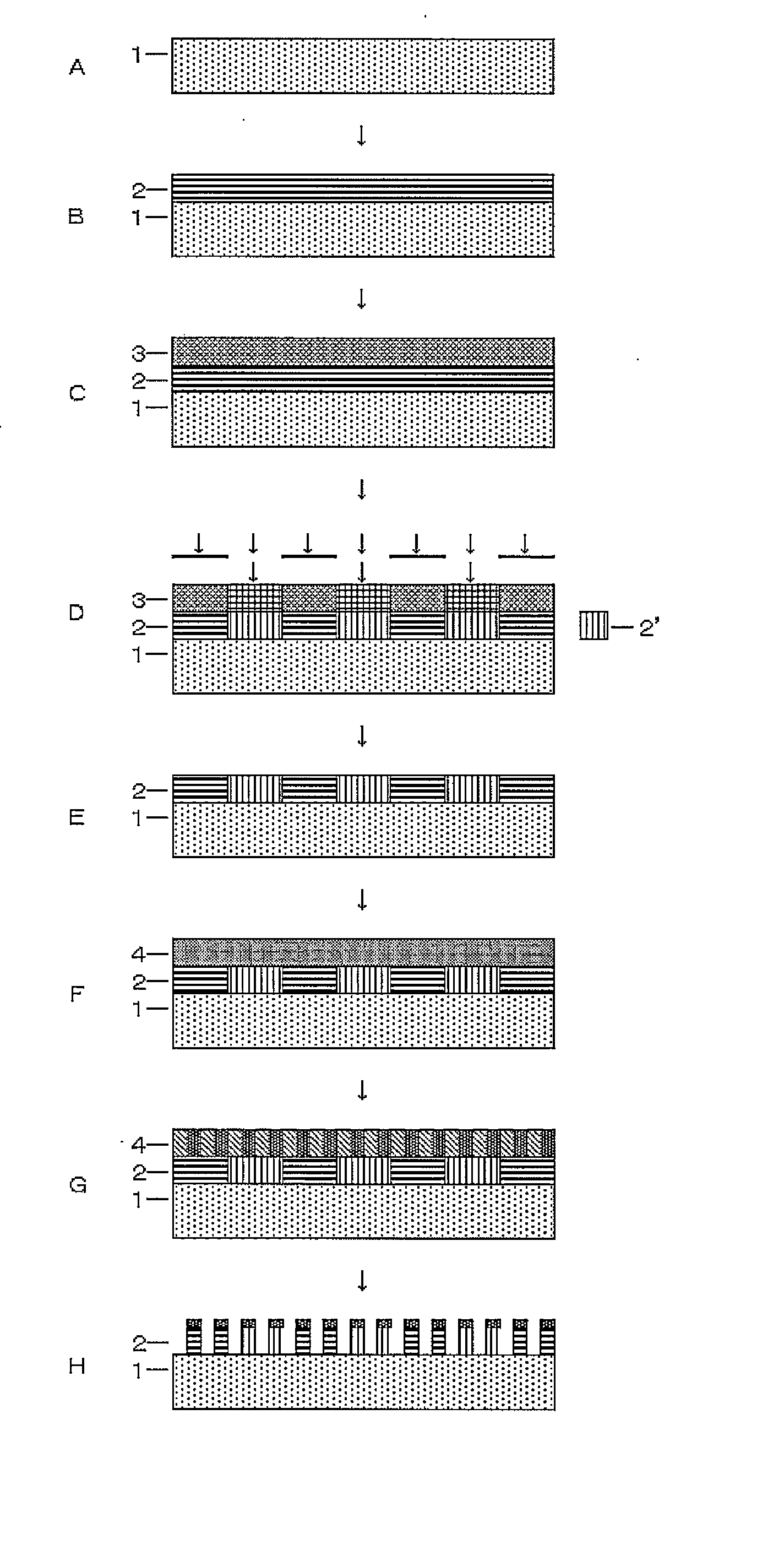
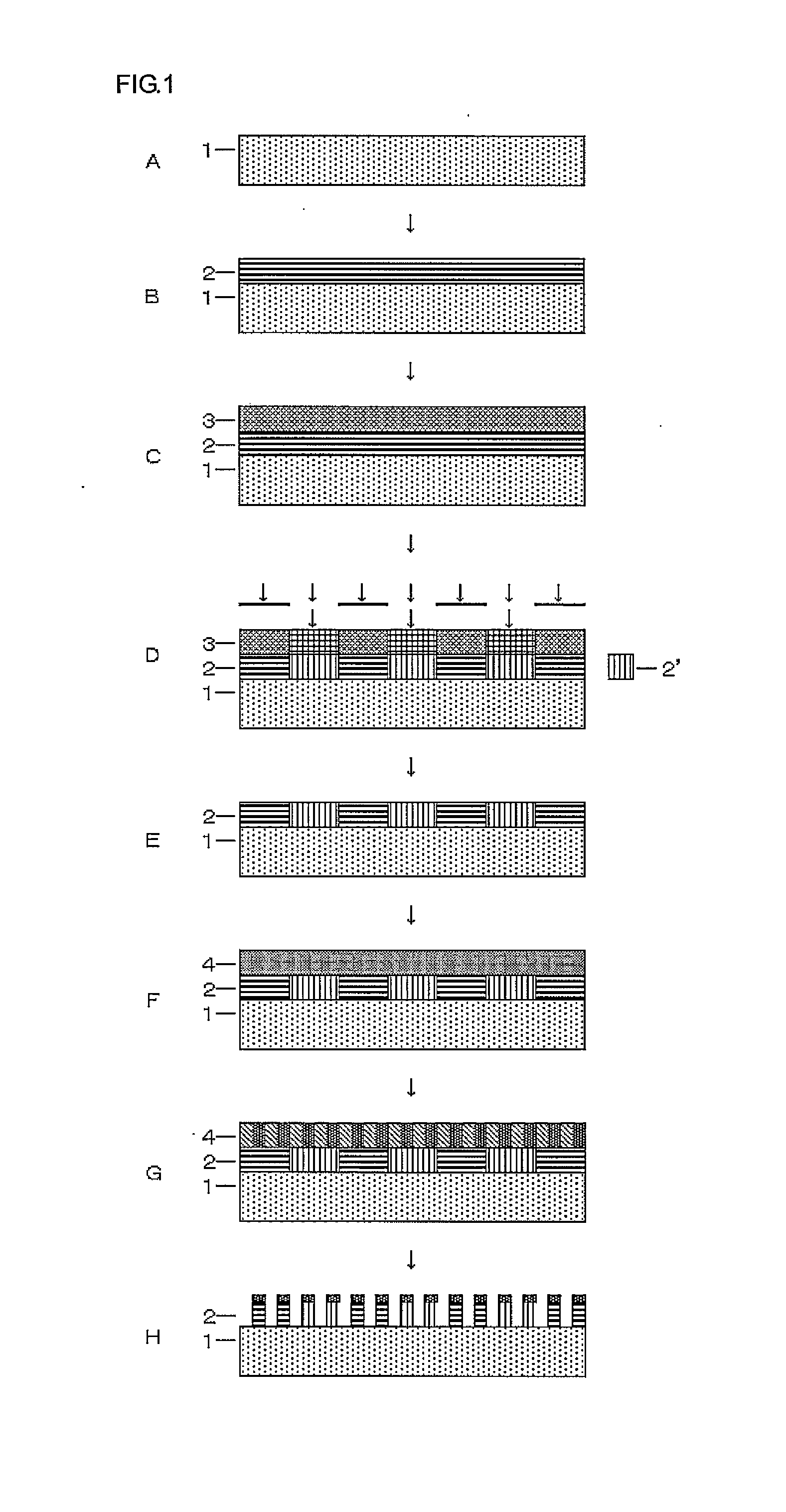
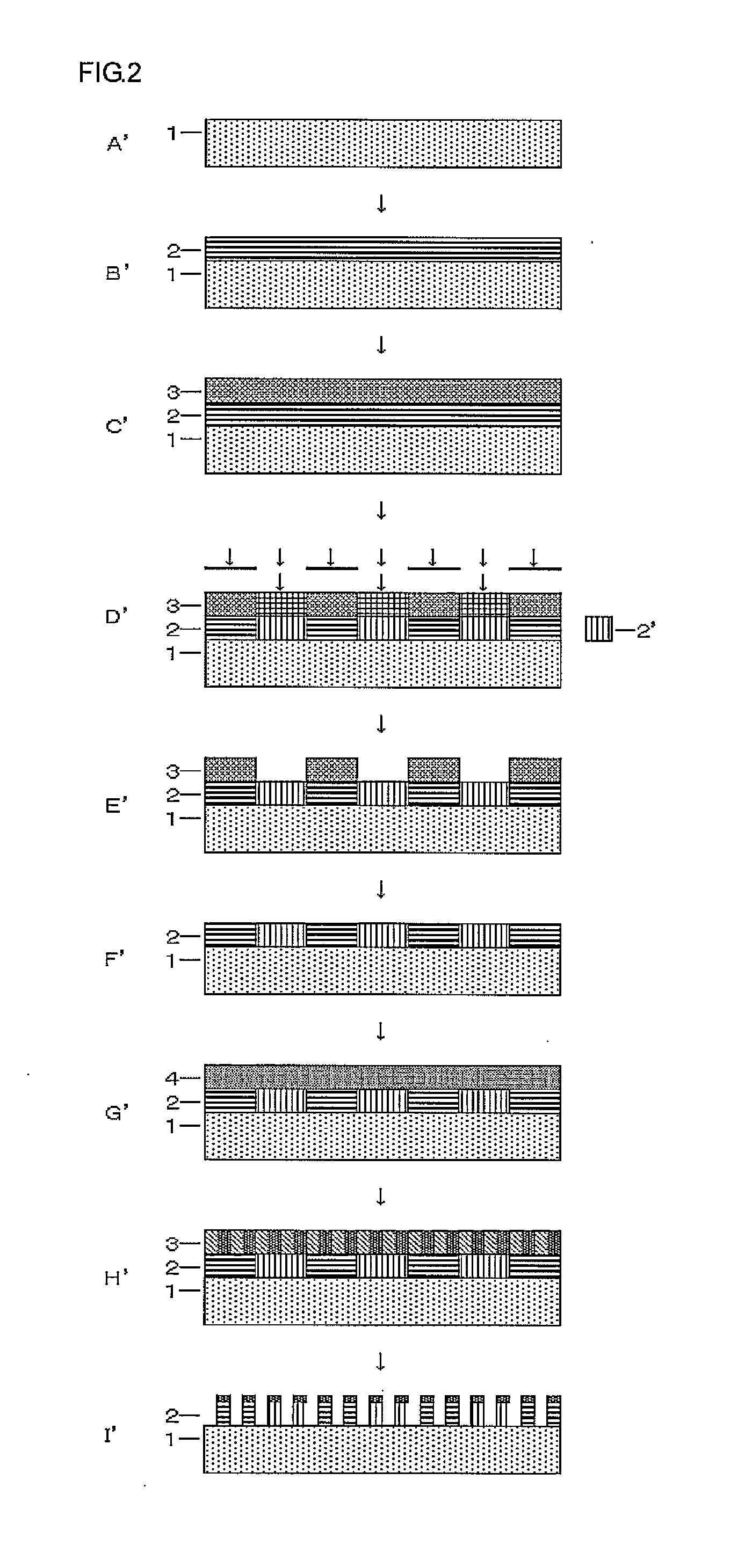
Image

Examples
synthesis example 1-1
[0149]Into a mixture of 220 g of methanol, 0.2 g of methanesulfonic acid, and 80 g of deionized water was added a mixture of 25.9 g of Monomer 101, 41.9 g of Monomer 102, and 9.5 g of Monomer 120; and then, they were kept at 40° C. for 12 hours to carry out the hydrolysis condensation reaction. After the reaction, 200 g of propylene glycol ethyl ether (PGEE) was added thereinto; and then, the by-produced alcohol was distilled out under reduced pressure. Then, 1000 mL of ethyl acetate and 300 g of PGEE were added thereinto to separate the water layer. To the remained organic layer was added 100 mL of ion-exchanged water; and then, the resulting mixture was stirred, settled, and separated into the layers. This operation was repeated for three times. The remained organic layer was concentrated under reduced pressure to obtain 330 g of PGEE solution containing the silicon-containing compound 1-1 (compound concentration of 10%). The polystyrene-equivalent molecular weight of this compoun...
synthesis example 1-17
[0151]Into a mixture of 400 g of ethanol, 5 g of 25% tetramethyl ammonium hydroxide, and 200 g of deionized water was added a mixture of 20.4 g of Monomer 101, 7.6 g of Monomer 102, and 95.5 g of Monomer 128; and then, they were kept at 40° C. for 4 hours to carry out the hydrolysis condensation reaction. After the reaction, 2 g of acetic acid was added thereinto for neutralization, and then, the by-produced alcohol was distilled out under reduced pressure. Then, 1200 mL of ethyl acetate and 400 g of PGEE were added thereinto to separate the water layer. To the remained organic layer was added 100 mL of ion-exchanged water; and then, the resulting mixture was stirred, settled, and separated into the layers. This operation was repeated for three times. The remained organic layer was concentrated under reduced pressure to obtain 410 g of PGEE solution containing the silicon-containing compound 1-17 (compound concentration of 20%). The polystyrene-equivalent molecular weight of this co...
synthesis example 1-25
[0153]Into a mixture of 120 g of methanol, 0.1 g of 70% nitric acid, and 60 g of deionized water was added a mixture of 5.0 g of Monomer 100, 3.4 g of Monomer 101, and 68.5 g of Monomer 102; and then, they were kept at 40° C. for 12 hours to carry out the hydrolysis condensation reaction. After the reaction, 300 g of PGEE was added thereinto; and then, the by-produced alcohol and excess water were distilled out under reduced pressure to obtain 310 g of PGEE solution containing the silicon-containing film composition 1-25 (polymer concentration of 10%). The polystyrene-equivalent molecular weight of this compound was measured to be Mw=2,200.
[0154]Synthesis Example 1-26 to Synthesis Example 1-30 were carried out by using the monomers shown in Table 1 under the conditions similar to those in Synthesis Example 1-25 to obtain each of the intended products.
TABLE 1SynthesisExampleRaw materials for reactionMw1-1 [Monomer 101]: 25.9 g, [Monomer 102]: 41.9 g, [Monomer 120]: 9.5 g2,2001-2 [Mon...
PUM
| Property | Measurement | Unit |
|---|---|---|
| Structure | aaaaa | aaaaa |
Abstract
Description
Claims
Application Information