Granular polycrystalline silicon and production thereof

a technology of polycrystalline silicon and granular polycrystalline silicon, which is applied in the direction of cellulosic plastic layered products, natural mineral layered products, transportation and packaging, etc., can solve the problems of increased production costs, affecting the quality of granules, so as to reduce production costs, reduce sputtering, and reduce the effect of sputtering

Active Publication Date: 2013-11-07
WACKER CHEM GMBH
View PDF4 Cites 18 Cited by
  • Summary
  • Abstract
  • Description
  • Claims
  • Application Information

AI Technical Summary

Benefits of technology

[0062]In addition, the inventive granular polysilicon—as described above—has a low hydrogen content. No thermal aftertreatment of the granular polysilicon is required. This leads to much lower sputtering in the course of melting. The granular silicon can be produced less expensively by dispensing with a thermal aftertreatment step with high temperatures.
[0063]The inventive granular polysilicon preferably has a thin oxide layer on the surface. The thickness of the oxide layer is preferably less than 3 atom layers and leads to better melting characteristics, lower dislocation rates and fewer crystal defects.

Problems solved by technology

The granular polysilicon nowadays produced on a large scale has a porous structure, and two seriously disadvantageous properties resulting from this:
This gas is released in the course of melting and disrupts the further processing of the granular polysilicon.
However, as described in U.S. Pat. No. 5,242,671, an additional working step is needed, which increases the production costs and additionally causes additional contamination of the granules.
The granular polysilicon is not particularly abrasion-resistant.
This means that the handling of the granules, for example in the course of transport to the user, gives rise to fine silicon dust.
This dust is disruptive in several ways:
it is disruptive in the further processing of the granular polysilicon since it floats as the granules are melted;
it is disruptive in the course of transport of the granular polysilicon within the production plant because it causes deposit formation on pipelines and results in blockage of valves;
Abrasion already leads to losses in the fluidized bed in the course of production of the granular polysilicon.
This ultrafine dust can partly be removed from the product, but this likewise means inconvenience, material loss and hence additional costs.
This and the lower level of abrasion lead to increased yields, since barely any fine dust is discharged from the fluidized bed, this always leading to a material loss in known processes.
However, the granular polysilicon known from the prior art does not have particularly good pulling properties (melt properties, lead frequencies, lead times).
In fluidized beds without a fixed bed zone in the bottom region, the greater movement of solids apparently results in contamination through the bottom region.
The silicon-silicon material pair between roll and milling material, however, leads to high wear of the silicon layer on the rolls, such that only short service lives of the machine are possible before the rolls have to be exchanged.
Economically viable production of seed is thus impossible.
A significant improvement with regard to roll wear is provided by the use of rolls with a hard metal surface and matched roll gap geometry, as described in DE 102004048948, but this results in contamination of the seed with B, C, Zn, Ti, Mg, W, Fe, Co, Sb and Zr.
The use of a seed mixture of screen undersize and seed ground with roll crushers ensures reduced contamination, but this is always still too high for processes such as GFZ pulling or for crucible pulling processes in the semiconductor industry.

Method used


Image

  • Granular polycrystalline silicon and production thereof
  • Granular polycrystalline silicon and production thereof
  • Granular polycrystalline silicon and production thereof

Examples


examples

[0154]Numerous experiments were conducted with different process conditions.

[0155]The inventive examples and comparative examples with all important process parameters and characterization data for the granules produced can be found in tables 1-3.

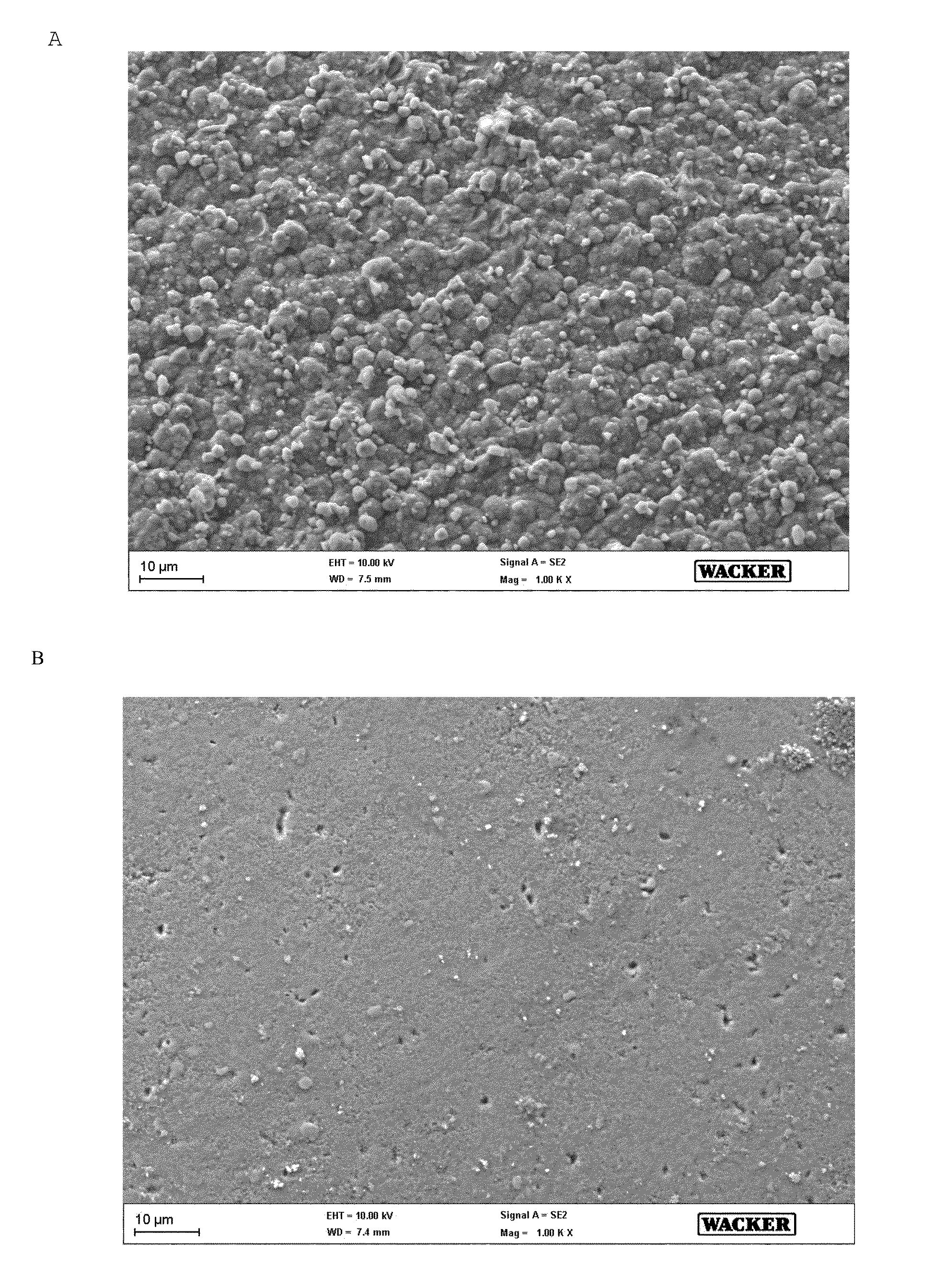
[0156]Table 1 shows positive examples 1 and 2 for crystal form: radiating acicular crystal aggregates and comparative example (negative example) 1 for crystal form: radiating acicular and parallel crystal aggregates.

[0157]Table 2 shows positive example 3 crystal form: radiating acicular crystal aggregates in the particle interior and acicular crystals arranged in parallel in a surrounding thin layer, and comparative example 2 for crystal form: radiating acicular crystal aggregates in the particle interior and acicular crystals arranged in parallel and radially in a surrounding thin layer.

[0158]Table 3 shows positive example 4 and comparative example 3 for crystal form: acicular crystals arranged in parallel.

TABLE 1Negative example 11Positiv...


PUM

PropertyMeasurementUnit
sizeaaaaaaaaaa
particle sizeaaaaaaaaaa
sizeaaaaaaaaaa

Abstract

Granular polycrystalline silicon includes a compact matrix including radiating acicular crystal aggregates of crystal size from 0.001-200 μm. A process for producing granular polycrystalline silicon includes producing granular silicon in a fluidized bed reactor from a gas mixture containing TCS (20-29 mol %) and hydrogen at a fluidized bed temperature of 900-970° C., dividing the granular silicon in a screen system having at least one screen deck into at least two screen fractions, the smallest screen fraction being ground in a grinding system to give seed particles having a size of 100-1500 μm and a mass-based median value from 400 to 900 μm, and these seed particles being supplied to fluidized bed reactor, and a further screen fraction being supplied to a fluidized bed reactor, and being surface-treated with a gas mixture containing TCS (5.1-10 mol %) and hydrogen at a fluidized bed temperature of 870-990° C.

Description

BACKGROUND OF THE INVENTION[0001]The invention relates to granular polycrystalline silicon and to the production thereof.[0002]Granular polycrystalline silicon or granular polysilicon for short is an alternative to the polysilicon produced in the Siemens process. While the polysilicon in the Siemens process is obtained as a cylindrical silicon rod which has to be comminuted prior to further use thereof in a time-consuming and costly manner to give what is called chip poly, and may again have to be purified, granular polysilicon has bulk material properties and can be used directly as a raw material, for example for single crystal production for the photovoltaics and electronics industry.[0003]Granular polysilicon is produced in a fluidized bed reactor. This is accomplished by fluidization of silicon particles by means of a gas flow in a fluidized bed, the latter being heated to high temperatures by means of a heating apparatus. Addition of a silicon-containing reaction gas results i...

Claims


Application Information

Patent Timeline
Patent Type & Authority Applications(United States)
IPC IPC(8): C01B33/02C23C16/24C23C16/442
CPCC01B33/02C23C16/442C23C16/24C01B33/03C01P2002/90C01P2004/03C01P2004/45C01P2004/50C01P2006/12C01P2006/80Y10T428/2982B01J8/18B82B1/00B82B3/00
Inventor HERTLEIN, HARALDHAUSWIRTH, RAINERWEIDHAUS, DIETER
Owner WACKER CHEM GMBH
Why Eureka
Try Eureka