

Method
a microneedle and needle technology, applied in the field of microneedle making, can solve the problems of poor compliance, nocosomial infection potential, logistical obstacles, cost, storage, distribution and disposal of used sharps, etc., and achieve the effects of improving the service life, and improving the quality of the produ
- Summary
- Abstract
- Description
- Claims
- Application Information
AI Technical Summary
Benefits of technology
Problems solved by technology
Method used
Image

Examples
example 1
Microneedle Preparation
Step 1. Microneedle Mould Preparation
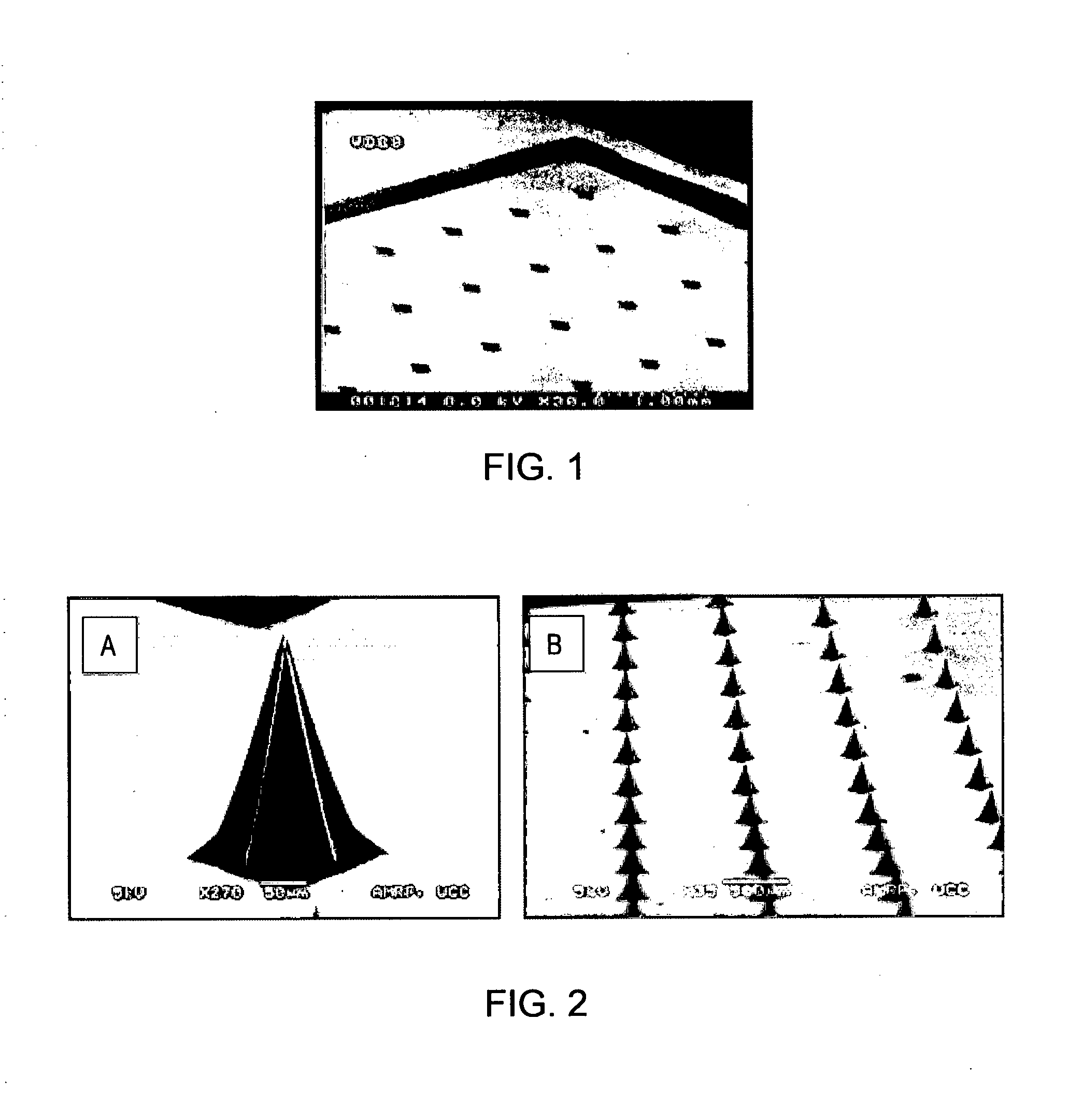
[0173]A master silicon microneedle array was manufactured by a silicon wet etching method (as described in U.S.2007 / 0134829A1 and Wilke el al (2005) Microelectronics Journal 36:650-656). Microneedle moulds were created from the master silicon microneedle array by pouring PDMS (polydimethylsiloxane) over the silicon array, curing at an elevated temperature (e.g. 100° C. for one hour) and then peeling the flexible PDMS mould from the master silicon array. FIG. 1 shows a scanning electron microscopy image of an inverted PDMS mould produced by this method.
Step 2. Filling the PDMS Mould By Spraying A Mixture of Material For Microneedle Construction
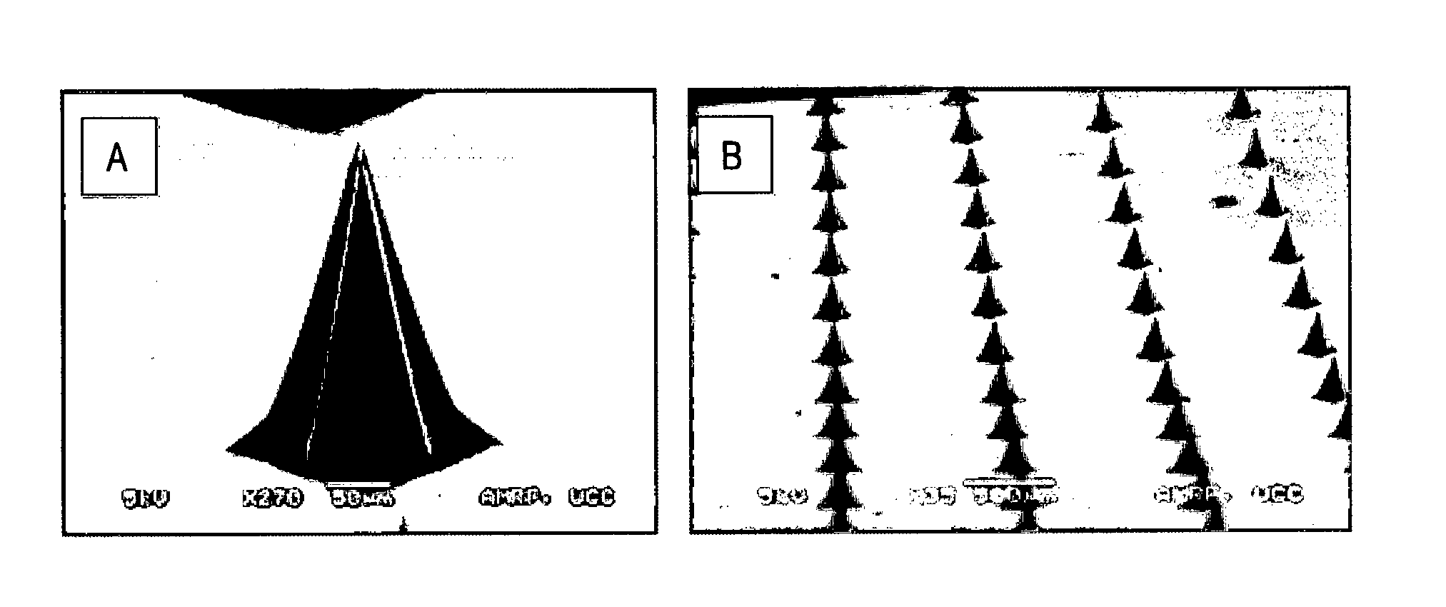
[0174]A mixture, containing the material of construction, was prepared at a concentration of suitable viscosity for atomisation. Mixtures were atomised using a Schlick nozzle 970 S8, or equivalent, fitted with a 0.5 mm bore. An atomisation air setting of 2, gas pressure of 0.25 bars (a...
example 2
Preparation of Dissolvable Microneedles From A Range of Materials
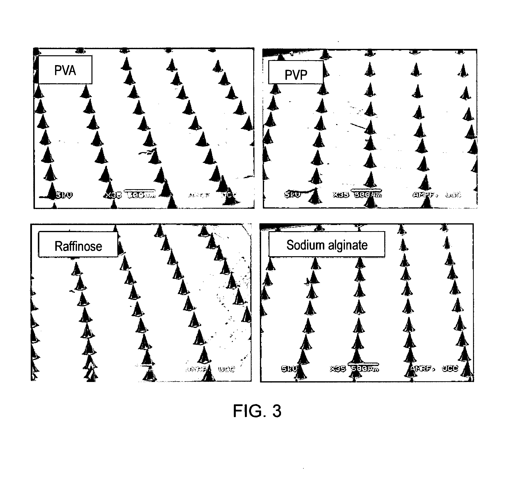
[0178]The method of preparation described in Example 1 can be used to prepare microneedles from a variety of dissolvable moieties such as polymers, cellulosics, sugars, polyols and alginic acid and its derivatives. FIG. 3 shows microneedles arrays prepared from polyvinyl alcohol (PVA), polyvinyl pyrrolidone (PVP), raffinose and sodium alginate.
[0179]Microneedles were prepared from 1% w / v aqueous solutions of PVA, PVP and raffinose and 0.35% w / v sodium alginate. Solutions were filter sterilised through a 0.4 m filter prior to atomisation when live virus vaccines were incorporated in the formulation. Solutions were atomised using a Schlick nozzle 970 S8 fitted with a 0.5 mm bore, an atomisation air setting of 2 and gas pressure of 0.25 bars (air / nitrogen). The nozzle was positioned at a distance of 3.5 cm from the PDMS mould. The moulds were passed under the spray. Spray times of less than 1 second were used. After spray...
example 3
Preparation of Microneedles Comprising Layers of Different Materials
[0180]The method of preparation described in Example 1 can be used to prepare microneedles composed of distinct layers of material. To prove this claim, layers of material were sprayed into the PDMS moulds using fluorescent materials that could be identified by fluorescent microscopy; red fluospheres and green fluorescein. FIG. 4 shows two ways these layers can be organised.
[0181]Microneedles in FIG. 4A were prepared by an initial rapid spray (<1 second) of a mixture of red fluospheres loaded in an aqueous solution of trehalose (1% w / v), followed by a drying step, followed by a 5 second spray of a mixture of fluoroscein loaded in an aqueous solution of trehalose (1% w / v) followed by a drying step. Each layer was left to dry for 5 minutes prior to application of the next layer. The backing layer of a solution of CMC (5% w / v) and (0.1% v / v) glycerine was applied using a syringe. The microneedle array was left to dry o...
PUM
| Property | Measurement | Unit |
|---|---|---|
| height | aaaaa | aaaaa |
| height | aaaaa | aaaaa |
| distance | aaaaa | aaaaa |
Abstract
Description
Claims
Application Information