
Liquid crystal compound having fluorovinyl group, liquid crystal composition and liquid crystal display device

a liquid crystal compound and fluorovinyl group technology, which is applied in the preparation of organic compounds, chemistry apparatus and processes, and chemical instruments and processes, etc., can solve the problems of compound having an insufficiently high clearing point, long life of the device, and small electric power consumption of the device, etc., to achieve high clearing point, small viscosity, and high heat resistance.

Active Publication Date: 2014-01-23
JNC CORP +1
View PDF1 Cites 2 Cited by
  • Summary
  • Abstract
  • Description
  • Claims
  • Application Information

AI Technical Summary

Benefits of technology

The first advantage of this patent is to provide a liquid crystal compound that has high stability, a high clearing point, a low minimum temperature of liquid crystal phase, a small viscosity, a suitable optical anisotropy, a large dielectric anisotropy, a suitable elastic constant, and an excellent solubility in other liquid crystal compounds. Additionally, it provides a compound with a large dielectric anisotropy and a high clearing point. The second advantage is to provide a liquid crystal composition containing the compound that has a high maximum temperature of a nematic phase, a low minimum temperature of the nematic phase, a small viscosity, a suitable optical anisotropy, a large dielectric anisotropy, and a suitable elastic constant. The third advantage is to provide a liquid crystal display device using this composition that has a wide temperature range, a short response time, a large voltage holding ratio, a large contrast ratio, and a long lifetime.

Problems solved by technology

Thus, a lifetime of the device becomes long.
Thus, an electric power consumption of the device becomes small.
However, the compound has an insufficiently high clearing point.
However, the compound has an insufficiently large dielectric anisotropy, and therefore a liquid crystal composition containing the compound presumably cannot satisfy a threshold voltage required by a commercially available device.
However, the compound has an insufficiently high clearing point.

Method used


Image

  • Liquid crystal compound having fluorovinyl group, liquid crystal composition and liquid crystal display device
  • Liquid crystal compound having fluorovinyl group, liquid crystal composition and liquid crystal display device
  • Liquid crystal compound having fluorovinyl group, liquid crystal composition and liquid crystal display device

Examples


example 1

Synthesis of Compound

No. 1-1-11

[0186]

First Step

[0187]In a 500 mL recovery flask, 6.00 g (15.7 mmol) of aryl bromide (T-1) was weighed, subjected to heating drying at 70° C. under reduced pressure for 2 hours, allowed to be cooled to room temperature, subjected to substitution to be under an argon atmosphere, and then dissolved into anhydrous THF (120 mL), and cooled to −78° C. To the solution, 4.80 mL (20.8 mmol) of triisopropyl borate was added, 12.5 mL (20.6 mmol) of hexane solution of 1.65 M n-butyllithium was slowly added dropwise, and the resulting mixture was stirred at −78° C. for 2 hours. To the reaction mixture, 1 M hydrochloric acid aqueous solution (90 mL) and ethyl acetate (120 mL) were added, and the resulting mixture was stirred at room temperature for 10 minutes. After liquids were separated, an aqueous layer was extracted with ethyl acetate (90 mL, twice), combined organic layers were sequentially washed with a saturated aqueous solution of sodium hydrogencarbonate (...

example 2

Synthesis of Compound

No. 1-1-12

[0193]

[0194]In a 50 mL recovery flask, 5.25 g (13.7 mmol) of compound (No. 1-1-11) was weighed, subjected to substitution to be under an argon atmosphere, and then dissolved into anhydrous THF (140 mL), and cooled to −78° C. To the solution, 15.5 mL (16.9 mmol) of diethyl ether solution of 1.09 M methyllithium was added, and the resulting mixture was stirred at −78° C. for 3o minutes. To the reaction mixture, 30% ammonium chloride aqueous solution (100 mL) was added, liquids were separated, a sodium chloride aqueous solution (20 mL) was added to an aqueous layer, and the aqueous layer was extracted with ethyl acetate (120 mL, twice). Combined organic layers were sequentially washed with a 18% sodium chloride aqueous solution (100 mL) and a saturated sodium chloride aqueous solution (100 mL), dried, and then concentrated under reduced pressure. The resulting solid was purified with automated medium pressure column chromatography made by Yamazen Corporat...

example 3

Synthesis of Compound

No. 1-1-13

[0200]

First Step

[0201]In a 50 mL recovery flask, 319 mg (0.835 mmol) of compound (No. 1-1-11) was weighed, subjected to substitution to be under an argon atmosphere, and then dissolved into anhydrous THF (4.0 mL), and cooled to −78° C. To the solution, 2.0 mL (1.0 mmol) of benzene / cyclohexane (volume ratio=9 / 1) mixed solution of 0.50 M ethyllithium was added, and the resulting mixture was stirred at −78° C. for 1 hour, and further at 0° C. for 1 hour. To the reaction mixture, a saturated ammonium chloride aqueous solution (3.0 mL) was added, and an aqueous layer was extracted with ethyl acetate (5.0 mL, once, 3.0 mL, twice). Combined organic layers were sequentially washed with pure water (3.0 mL) and a saturated sodium chloride aqueous solution (3.0 mL), dried, and then concentrated under reduced pressure. The resulting solid was purified with automated medium pressure column chromatography made by Yamazen Corporation (column size L+L (silica gel 60 g...


PUM

PropertyMeasurementUnit
Compositionaaaaaaaaaa

Abstract

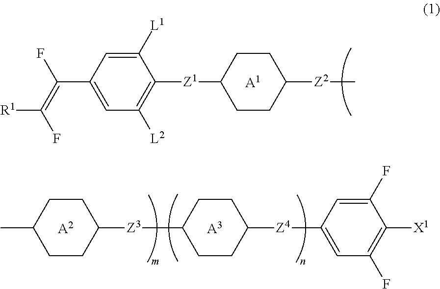
A liquid crystal compound having a high stability to heat, light and so forth, a high clearing point, a low minimum temperature of a liquid crystal phase, a small viscosity, a suitable optical anisotropy, a large dielectric anisotropy, a suitable elastic constant and an excellent solubility in other liquid crystal compounds, a liquid crystal composition containing the compound, and a liquid crystal display device including the composition. The compound is represented by formula (1):wherein, for example, R1 is fluorine or alkyl having 1 to 10 carbons; ring A1 and ring A2 are 1,4-phenylene, or 1,4-phenylene in which at least one of hydrogen is replaced by fluorine; Z1, Z2 and Z3 are a single bond; L1 and L2 are hydrogen or fluorine; X1 is fluorine or —CF3; and m is 1, and n is 0.

Description

TECHNICAL FIELD[0001]The invention relates to a liquid crystal compound, a liquid crystal composition and a liquid crystal display device. More specifically, the invention relates to a compound having a fluorovinyl group, a liquid crystal composition containing the compound and having a nematic phase, and a liquid crystal display device including the composition.BACKGROUND ART[0002]A liquid crystal display device is widely utilized for a display of a personal computer, a television and so forth. The device utilizes optical anisotropy, dielectric anisotropy or the like of a liquid crystal compound. As an operating mode of the liquid crystal display device, various modes are known, such as a phase change (PC) mode, a twisted nematic (TN) mode, a super twisted nematic (STN) mode, a bistable twisted nematic (BTN) mode, an electrically controlled birefringence (ECB) mode, an optically compensated bend (OCB) mode, an in-plane switching (IPS) mode, a vertical alignment (VA) mode and a poly...

Claims


Application Information

Patent Timeline
IPC IPC(8): C09K19/08C09K19/34C09K19/20C09K19/30C09K19/14C09K19/12C09K19/06
CPCC09K19/08C09K19/126C09K19/3402C09K19/3469C09K19/06C09K19/3444C09K19/3003C09K19/14C09K19/2007C09K19/12C09K19/322C09K2019/0459C09K2019/0466C09K2019/123C09K2019/2035C09K2019/301C09K2019/3016C09K2019/304C09K2019/308C09K2019/3422C09K2019/3425C09K2323/00
Inventor GOTOH, YASUYUKIKIMURA, KEIJI
Owner JNC CORP
Learn More