However, when the carrier concentration in the drift layer 23 increases, turn-off loss increases.
However, when positively using the IE effect in a
trench gate type IGBT having an n mesa structure with a high
aspect ratio, there arises a manufacturing problem that it is not easy to form a
deep trench and a narrow mesa width, but furthermore, there are also characteristics problems to be described hereafter.
This causes a problem that the
rate of rise of current at turn-on time becomes extremely high.
However, a structure with high collector-
gate capacitance is often such that the rising of the gate potential by a rise in collector current is high.
In this way, when a rise in collector current cannot be controlled by the
gate resistance, as well as the rate of decrease of the voltage between the collector and emitter of the IGBT after the collector current has reached a predetermined value becoming higher, the rate of rise of reverse voltage (dV / dt) at the time of
reverse recovery action of
reflux diode of the opposing arm in the
inverter circuit increases, thus leading to a problem that
radiation noise increases.
Because of this, the rate of rise of the
diode reverse voltage increases, and the previously described
noise is generated, as a result of which the rate of decrease of the voltage between the collector and emitter of the IGBT increases.
This amount of overshoot current is made up for by
reverse current swept out from the
diode, but when it is difficult to supply the
reverse current, reverse voltage is applied to the diode, and the IGBT collector voltage starts to decrease compared with the
bus voltage.
In the event that the rise in the reverse voltage of the diode is insufficient, it is not possible to
supply current necessary as collector current determined by the
gate voltage and collector voltage of the IGBT at that moment, and it is attempted to
supply current from a power source through the load
inductance.
As the collector voltage continues to decrease, the bias conditions of the IGBT change, the rate of rise of collector current becomes dull, and consequently, the
rate of increase of the
reverse current of the diode also becomes dull.
Consequently, as the rate of rise of turn-on current is high, and the rate of decrease of turn-on voltage is low, there is a tendency for both noise and loss to become higher.
When the collector-gate
capacitance is extremely low, the rate of rise of collector voltage at turn-on time is high, and this becomes a main source of
radiation noise.
According to the above discussion, with the
trench gate type IGBT including the n-type mesa structure with high
aspect ratio and the floating p layer, when the
area ratio of the p base region is lowered in order to increase the surface carrier concentration of the IGBT for the purpose of improving the previously described trade-off relationship, an increase in radiation noise at turn-on time becomes a problem.
It is often the case that the rate of rise of reverse voltage of the
reflux diode particularly at low temperature time and low
current time is a decisive factor of noise.
Consequently, the rise of potential of the floating p layer itself is also low.
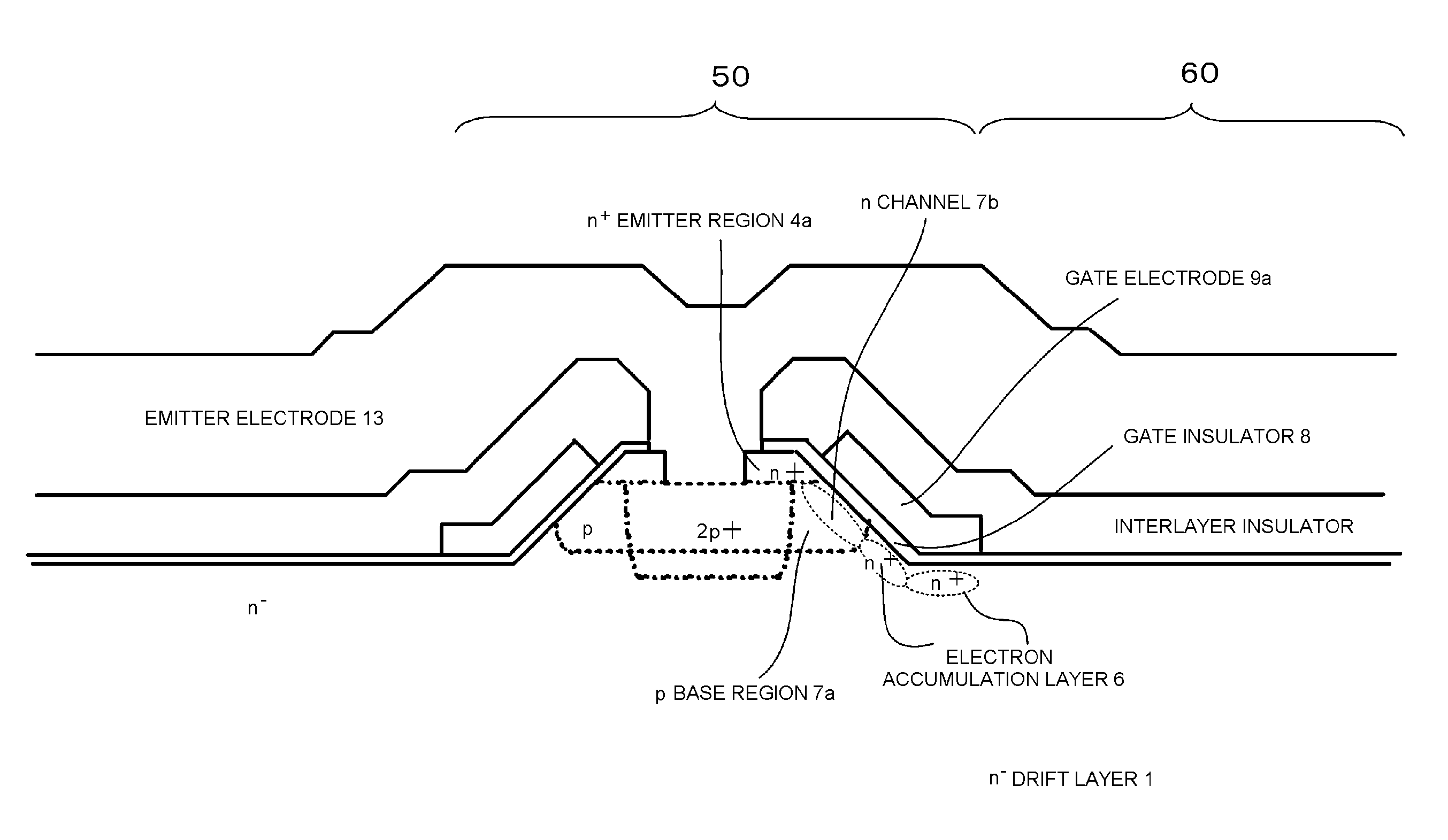
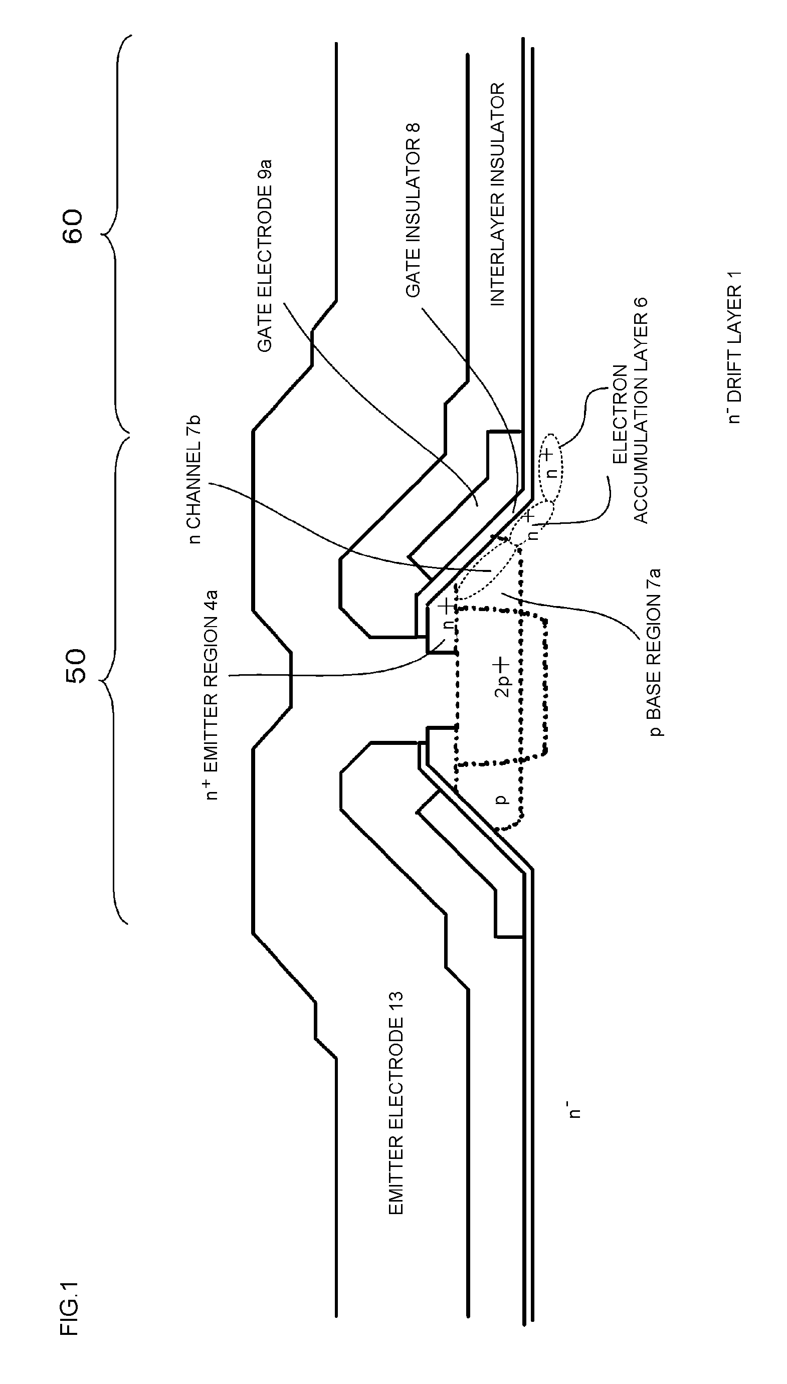
However, with this structure, the p base region exists on each side of the gate trench, meaning that there is a problem that the
area ratio per unit
cell of the p base region is twice as high as that in a normal
trench gate structure with the same trench
pitch.
Meanwhile, in a planar gate structure without using the floating p layer too, there exists a problem of the rising of gate potential by negative gate
capacitance.
In the planar gate type IGBT too, when the
area ratio of the p base region is reduced, hole
current density per unit
cell increases, and the rise of
silicon surface potential increases, thus causing a problem that current flowing around into the gate circuit via the
gate insulator immediately above the
silicon surface is caused to occur, thus raising the rate of rise of turn-on current.
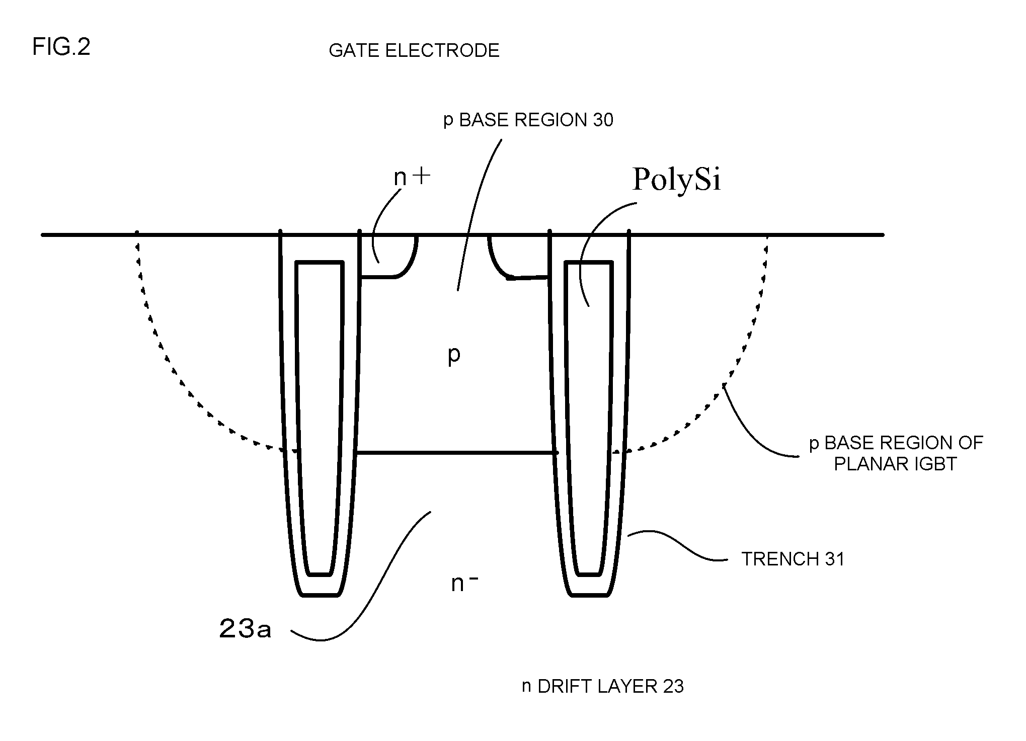
With regard to a trench gate type IGBT without using a floating p layer too, when a structure is adopted wherein, for example, the area ratio of a p base region is reduced, the trench width is widened, the gate width is widened, and the
aspect ratio of an n-type mesa region is increased, thus forming a vertically long structure, the potential of a
silicon surface in contact with a
gate insulator is likely to rise owing to a rise in hole
current density, and there arises a problem that current flowing around into the gate circuit becomes larger, thus raising the rate of rise of turn-on current, in the same way as previously described.

