Methane separation method, methane separation apparatus, and methane utilization system

a technology of methane separation and methane, which is applied in the direction of gaseous fuel, separation process, absorption purification/separation, etc., can solve the problems of gas separation operation cost, increase in initial cost, and large size, and achieve low separation cost, high efficiency, and reduce power load and membrane module cost

Inactive Publication Date: 2014-03-27
RES INST OF INNOVATIVE TECH FOR THE EARTH +1
View PDF2 Cites 0 Cited by
  • Summary
  • Abstract
  • Description
  • Claims
  • Application Information

AI Technical Summary

Benefits of technology

[0045]According to the first embodiment of the present invention, the mixed fluid in a gas-liquid mixed phase formed in the mixer is introduced into the first gas / liquid separator and the separated methane is recovered. Thereafter, the CO2-absorbed liquid is supplied to the inside of the membrane module, and the pressure outside the permeable membrane is lowered to a level lower than that inside the permeable membrane. Since the separation of carbon dioxide accelerates due to this configuration, methane can be separated and purified at high efficiency from the biogas containing high concentration of carbon dioxide. Therefore, the present invention is capable of reducing power load and membrane module cost and can carry out the separation / concentration of biogases at a low separation cost compared to the already available apparatuses that employ the PSA process, the dry membrane separation process, the chemical absorption method, or the like by adopting the membrane / absorption hybrid method. Since most methane contained in the biogas can be recovered merely by the first gas / liquid separator, simplification of the apparatus configuration and price reduction of the methane separation apparatus will be possible. In addition, power load can be reduced by lowering the flow rate of excessive CO2-absorbed liquid pouring out from the exhaust port of the membrane module down to a minimum level.
[0046]Various mixers capable of dispersing the biogas as minute bubbles in the absorbing liquid can be used as the aforementioned mixer. Specifically, stand alone mixers such as an ejector, a mixer, an aerator, and a packed bubble column of a gas-liquid co-current which is a gas-liquid contacting column where a filler is filled, or combined mixers that combine two or more of the above mixers can be used.
[0047]According to the second embodiment of the present invention, further improvements in the methane separation can be achieved since an excessive CO2-absorbed liquid discharged from the exhaust port of the membrane module is introduced to the second gas / liquid separator and the reseparation / recovering of the remaining trace amount of methane is carried out.
[0048]The third and fourth embodiments of the present invention contribute to the improvements in methane separation performance. It has become apparent due to the verification of the present inventors that at the time of carbon dioxide release in the regeneration step of the absorbing liquid, congestion of the membrane module prevents the release. In other words, the packing density of permeable membranes affects the performance of carbon dioxide release in the membrane module. The packing density of hollow fiber permeable membranes in the commercially available membrane modules is 30 to 70% and the interval between adjacent permeable membranes is too packed. For this reason, space between membranes will be covered with liquid membranes when the liquid flow rate is large which makes the release efficiency of carbon dioxide by the reduced pressure more impaired as it approaches the center. As a result, a large membrane area will be required causing a cost increase.
[0049]On the other hand, according to the third embodiment of the present invention, the packing density of permeable membranes is 30% or less (preferably 20% or less) which is sparse. Hence, it will be possible to enhance the release properties of carbon dioxide and to separate methane at high efficiency. In addition, according to the fourth embodiment of the present invention, the permeable membrane in the membrane module is segmented into small bundles for arrangement and each of the small bundles is arranged so as to retain uncongested space therebetween, and a packing density as a whole is 30% or less. Hence, it will be possible to make the packing density of permeable membranes sparse, enhance the release properties of carbon dioxide, and separate methane at high efficiency.
[0050]According to the fifth embodiment of the present invention, rapid narrowing down of the absorbing liquid generates a high speed flow causing intense negative pressure since at least an ejector is used as the aforementioned mixer, and biogases can be sucked into the absorbing liquid automatically without any power due to this negative pressure. Moreover, minute gas bubbles are formed instantly inside the absorbing liquid and the mixed fluid in a gas-liquid mixed phase is formed efficiently. As a result, a gas / liquid contacting surface area will increase and a large amount of carbon dioxide in the biogas can be absorbed by the absorbing liquid with a shorter contact time and a lesser amount of absorbing liquid compared to the conventional cases. As described so far, an optimum mixed fluid in a gas-liquid mixed phase can be formed and separated through gas / liquid separation and at the same time, the carbon dioxide contained in the biogas at high concentrations can be absorbed by the minimum amount of absorbing liquid. Hence, the methane separation can be carried out at high efficiency without supplying excessive amount of absorbing liquid to the permeable membranes. It will be possible to simplify the apparatus configuration and to reduce price and power cost when the aforementioned mixer is configured only with an ejector. Needless to say, more efficient mixing / absorption can be achieved by adding other mixing units to the ejector.

Problems solved by technology

In the low temperature processing method, the separation process involves the comings and goings of heat and it is not preferable from an economical viewpoint since an apparatus will be complex and also will be large in size if highly pure methane were to be obtained efficiently.
Accordingly, there has been a problem of increase in the initial cost as well as the operation cost for gas separation due to the absorption column for efficiently bringing the absorbing liquid into contact with the target gas and a large amount of heating energy required for the release.
Moreover, the requirement for a large amount of water for purifying biogases has also been a problem, although there is a so-called carbonate absorption process available which exploits the effect that carbon dioxide dissolves in water and uses high pressure water.
However, since the differences in the permeation rates among the membranes are exploited in the dry membrane separation process, it is necessary to increase the number of steps in the membrane module in order to obtain highly pure methane resulting in higher cost, which has been a problem.
However, in the PSA process, a pressure range in which an apparatus is operated needs to be set within a wide range of −90 KPaG to 0.7 MPaG in order to obtain highly pure methane, and thus the resulting high power cost is a problem.
In addition, recovery rate needs to be sacrificed in order to obtain highly pure methane which leads to the generation of a large amount of exhaust gas containing methane.
Accordingly, it will be necessary to install a combustion facility and the like to safely treat methane that is flammable resulting in a high cost for the separation process.
Moreover, even if methane can be released in the air safely, it will be a great disadvantage to release methane that has a high global warming potential into the atmosphere when considering the increase in the awareness of global environmental issues in recent years.
However, when applying the membrane / absorption hybrid method to biogases, a gas-liquid mixed phase of methane that does not dissolve in an absorbing liquid and the absorbing liquid is generated inside a permeable membrane since a target gas for separation containing gases to be separated such as carbon dioxide and methane is supplied together with the absorbing liquid to, for example, a membrane module, resulting in a decline of methane separation efficiency, which is a problem.
Moreover, since high concentration of carbon dioxide is contained in biogases, satisfactory release of the carbon dioxide absorbed in the absorbing liquid that permeated the permeable membrane of the membrane module is not achieved and the absorbing liquid returns to an absorbing-liquid circulation system without being regenerated satisfactorily, and thus a methane purification efficiency declines, which is also a problem.

Method used


Image

  • Methane separation method, methane separation apparatus, and methane utilization system
  • Methane separation method, methane separation apparatus, and methane utilization system
  • Methane separation method, methane separation apparatus, and methane utilization system

Examples


example 1

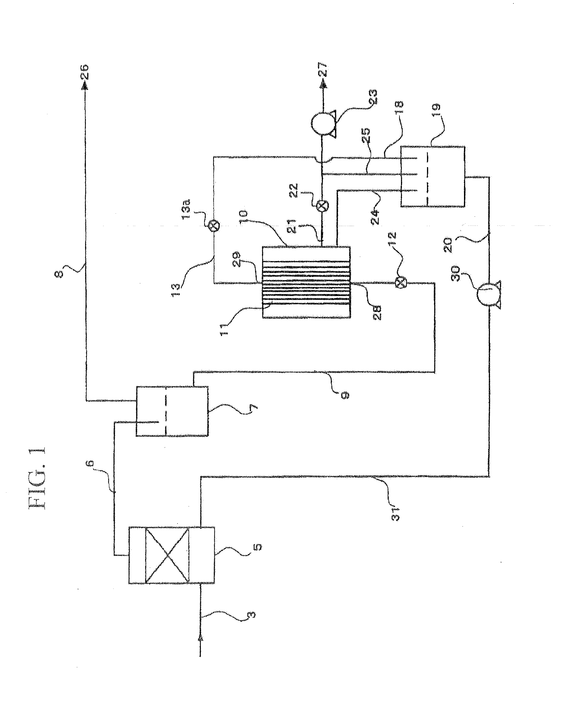
[0097]In Example 1, comparison test of the concentration of methane concentrated by mixers of 3 different kinds of absorption systems was carried out by using the methane separation apparatus of a one stage separation system shown in FIG. 1.

[0098]FIG. 5 is a comparison chart of concentrations of the concentrated methane obtained by conducting methane separation from the absorbing liquid that absorbed carbon dioxide using mixers of 3 different absorption systems. The longitudinal axis indicates the concentration of concentrated CH4 (%) that is separated. The transverse axis indicates the required membrane area (m2 / (Nl / min)), which is the surface area of a permeable membrane per unit flow rate of a biogas to be treated. More specifically, the required membrane area is defined by the following equation: Required membrane area=(surface area of permeable membrane installed in membrane module) [m2] / (biogas treatment flow rate) [Nl / min], and the lower value of required membrane area means ...

examples 2 to 5

[0103]In Examples 2 to 5, separation and purification of methane were carried out using the methane separation apparatus of a one stage separation system shown in FIG. 1.

[0104]Tables 1 to 4 show details of the respective conditions, in which Examples 2 to 5 were conducted.

TABLE 1Biogas treatment flow rateNl / min0.67Degree of vacuumkPaG−90.2CH4 concentration%98.4DEA temperature° C.29CH4 recovery rate%99.5Membrane aream20.062Required membrane aream2 / (Nl / min)0.09Flow rate of permeatingL / m2 · min40.6liquid per membrane areaGas / liquid ratio (Nl / L)0.27Absorbing liquid3 mol / l-DEAHollow fiber materialPolyethylene φ0.7 mmMembrane effective length [cm]47Pore size [nm]250Membrane filling rate [m2 / m2]0.096

TABLE 2Biogas treatment flow rateNl / min0.67Degree of vacuumkPaG−91.3CH4 concentration%98.2DEA temperature° C.29CH4 recovery rate%99.6Membrane aream20.062Required membrane aream2 / (Nl / min)0.09Flow rate of permeatingL / m2 · min28.4liquid per membrane areaGas / liquid ratio (Nl / L)0.27Absorbing liquid3...

example 6

[0108]In Example 6, the methane separation apparatus according to the present invention was compared with the apparatus of a conventional methane purification system in terms of gas separation performance, purification cost, and the like.

[0109]Table 5 compares the methane separation apparatus according to the present invention with the apparatus of a conventional methane purification system in terms of gas separation performance, purification cost, and the like.

TABLE 5Comparison of each systemDry membraneChemicalseparationabsorption methodMembrane / absorptionItemPSA processprocess(diethanolamine)hybrid methodOperating pressureNormal pressure0.6 to 0.7 MPaGNormal pressureNormal pressure(desorption −90 kPaG)(desorption −90 kPaG)CH4 concentration90%90%90%90%CH4 recovery rate90% (CH470% (CH4≈100% (no dependence on≈100% (no dependence onconcentration 90%)concentration 90%)CH4 concentration)CH4 concentration)Required power [kW]21202017Power unit consumption [kWh / m3]0.390.480.330.28N.B.) Ca...


PUM

PropertyMeasurementUnit
DEA flow rateaaaaaaaaaa
flow rateaaaaaaaaaa

Abstract

A methane separation method of the present invention at least includes: mixing the biogas and an absorbing liquid that absorbs carbon dioxide in a mixer so as to form a mixed fluid of a gas-liquid mixed phase; introducing the mixed fluid into a first gas / liquid separator so as to separate the mixed fluid through gas / liquid separation into methane and a CO2-absorbed liquid formed due to an absorption of the carbon dioxide by the absorbing liquid; recovering methane separated in the first gas / liquid separator; and supplying the CO2-absorbed liquid through a supply port of a membrane module comprised of a container and a plurality of hollow fiber permeable membranes built therein to inside of the membranes so as to make the CO2-absorbed liquid permeate the permeable membranes, and lowering a pressure outside the permeable membranes to a level lower than that inside the permeable membranes.

Description

[0001]This application is a divisional of application Ser. No. 12 / 295,780 filed Oct. 2, 2008, which in turn is the U.S. national phase of International Application No. PCT / JP2007 / 057564 filed 4 Apr. 2007 which designated the U.S. and claims priority to Japanese Patent Application No. 2006-103665 filed 4 Apr. 2006, the entire contents of each of which are hereby incorporated by reference.TECHNICAL FIELD[0002]The present invention relates to a methane separation method that separates methane from biogases such as a natural gas that has methane as its major component and is generated from underground due to the anaerobic fermentation by organisms, an underground fermentation gas produced by a natural anaerobic fermentation due to an underground burial of industrial and domestic wastes, and an artificial fermentation gas generated artificially and discharged from an anaerobic fermentation process, a methane separation apparatus that carries out the method, and a methane utilization syst...

Claims


Application Information

Patent Timeline
Patent Type & Authority Applications(United States)
IPC IPC(8): C07C7/11
CPCC07C7/11B01D3/101B01D19/0031B01D53/1425B01D53/1487B01D53/22B01D63/04B01D2257/504C10L3/10C10L3/102B01D63/043B01D2258/05Y02C20/40Y02P70/10
Inventor TOMIOKA, TAKAFUMIABE, TOSHIYUKISAKAI, TORUMANO, HIROSHIOKABE, KAZUHIRO
Owner RES INST OF INNOVATIVE TECH FOR THE EARTH
Why Eureka
Try Eureka