

Novel devices for effective and uniform shrinkage of tissues and their unique methods of use
a tissue and tissue technology, applied in the field of tissue shrinkage and tissue shrinkage to treat medical conditions, can solve the problems of loss of fullness, inability to completely relieve medical conditions in many patients, and ineffective treatment of urinary and fecal incontinence in the elderly,
- Summary
- Abstract
- Description
- Claims
- Application Information
AI Technical Summary
Benefits of technology
Problems solved by technology
Method used
Image

Examples
first embodiment
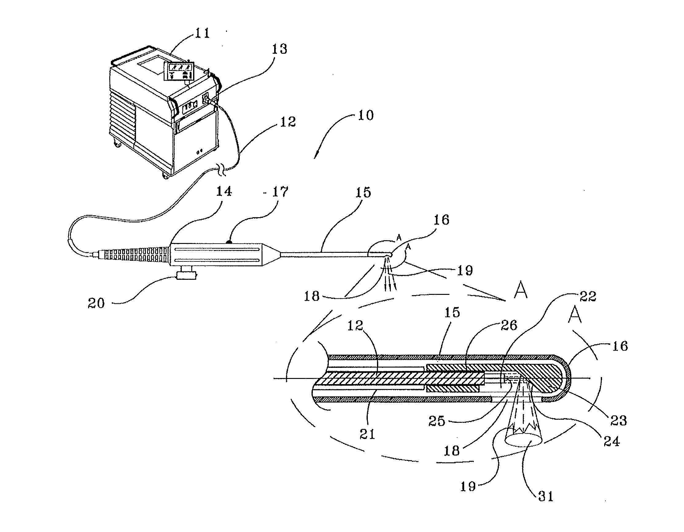
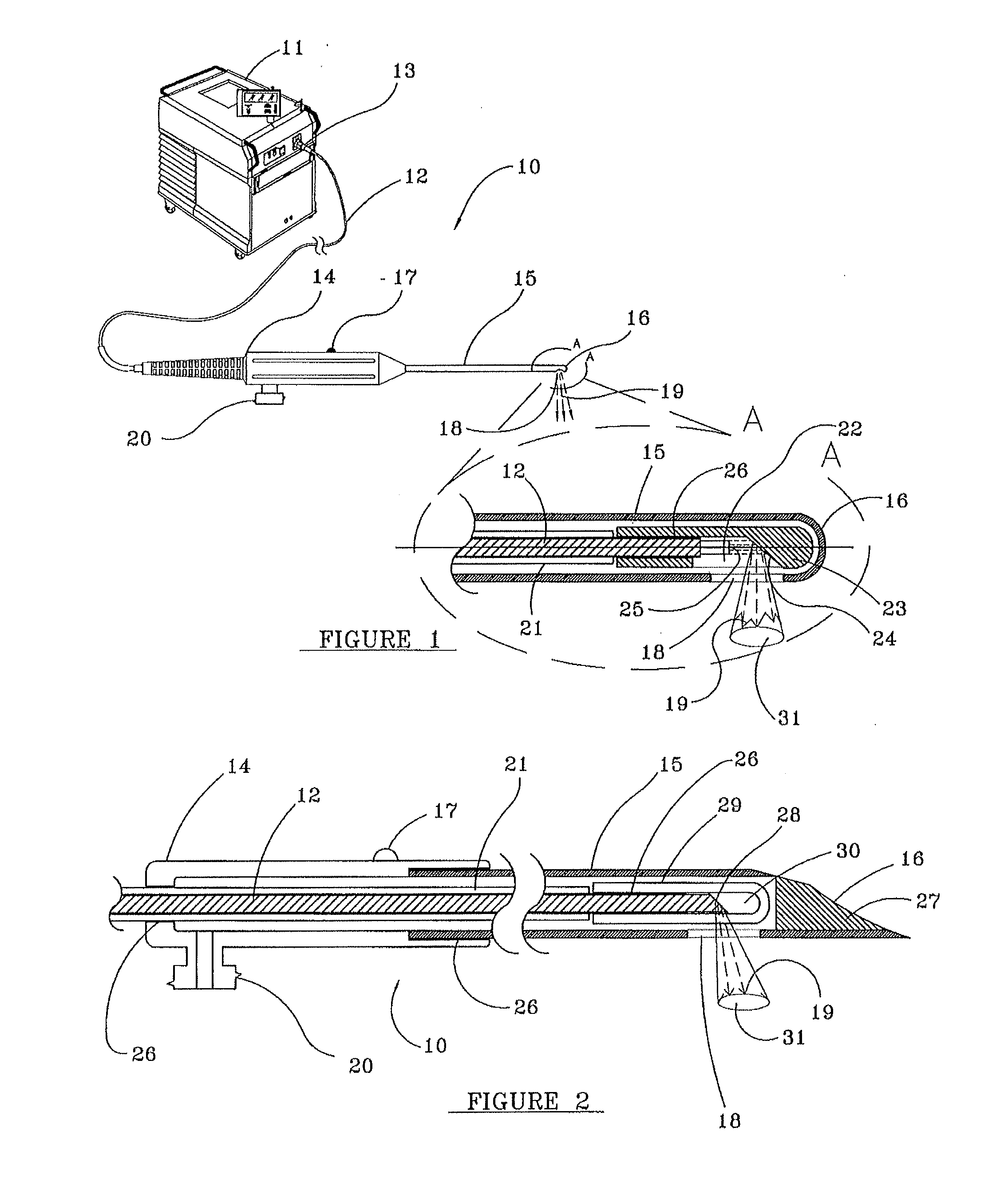
[0127]side firing device 10 suitable for practicing the present invention is illustrated in FIG. 1. Device 10 is comprised of laser energy source 11 and optical fiber 12. Connector 13 operably couples optical fiber 12 to laser energy source 11. Optical fiber 12 is fixedly and sealingly attached within the proximal end of handpiece 14 by adhesive 26, as known in the art, and extends through a hollow, longitudinal, passageway (not separately shown) in handpiece 14 and is in fluid communication with hollow metal or rigid plastic cannula 15, preferably of medical grade stainless steel, whose proximal end is fixedly attached by adhesive 26 within the distal end of handpiece 14.
[0128]The distal end 16 of cannula 15, as shown in FIG. 1, is rounded. Distal end 16 of cannula 15 may also be blunt, sharp, double-bevel needle-shaped, trocar shaped or of any other desired shape, as known in the art. Using a needle-like or sharp-ended cannula within a patient entails considerable risk to the pati...
second embodiment
[0139]side firing device 10 of the present invention is shown in FIG. 2. In this embodiment, distal end 16 of hollow cannula 15 is shaped like the distal end of a double beveled syringe needle, which cuts rather than making a puncture or hole through the skin, hastening healing and reducing bleeding and the risk of an infection. To prevent tissue from lodging in the opening at distal end 16 of cannula 15, plug 27 of an adhesive or other material, preferably heat resistant to any stray laser energy, may be used to fill distal end 16 of cannula 15, as known in the art.
[0140]Distal end 16 of hollow cannula 15 can also be blunt, round, conical or any other desired shape, as the use of a sharp or needle-like device within a patient requires imaging during its use and great care by the surgeon.
[0141]Buffer coating 21 and any optional polymer cladding have been removed from the distal end portion of optical fiber 12, and the distal end of optical fiber 12 has been ground and polished into ...
third embodiment
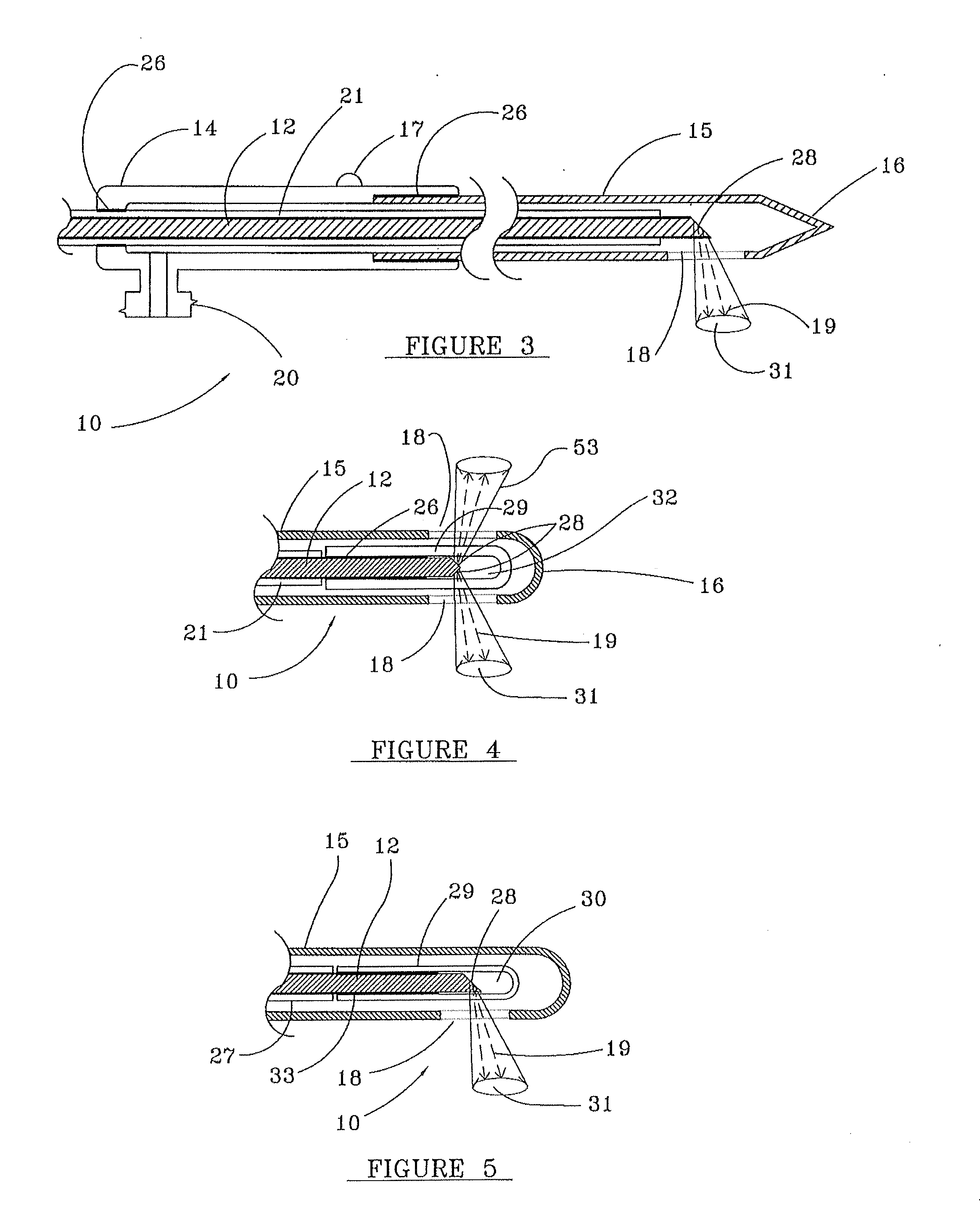
[0145]FIG. 3 illustrates side firing device 10 of the present invention. In this embodiment, no capillary tube 29 is utilized to sealingly encase the beveled, distal end surface 28 of optical fiber 12. As a result, no air pocket is created opposite beveled, distal end surface 28 of optical fiber 12.
[0146]Laser energy at wavelengths of 1400 to 1500 nm and 1800 to 11,000 nm are highly absorbed by aqueous liquids, such as sterile saline or water, which are commonly used as an irrigation fluid in endoscopic procedures. If ten or more watts of laser power at these wavelengths is transmitted through optical fiber 12, such wavelengths of laser energy cause a steam and / or gas bubble (not separately shown) to form, with each pulse of laser energy, opposite beveled, distal end surface 28 of optical fiber 12, from the vaporization of the aqueous irrigation liquid, blood, other body fluids and / or tissue.
[0147]The refractive index of the steam and / or gas bubble opposite beveled, distal end surfa...
PUM
 Abstract
Description
Claims
Application Information