Sensor Apparatus

a technology of sensor and insulating conductor, which is applied in the direction of power cables, cables, insulated conductors, etc., can solve the problems of insufficient resistance of the system to high pressure, unstable response of these sensors, and miniaturization of ises

Inactive Publication Date: 2014-06-12
UNITED SCI LLC
View PDF0 Cites 33 Cited by
  • Summary
  • Abstract
  • Description
  • Claims
  • Application Information

AI Technical Summary

Problems solved by technology

First, due to the flowing liquid junctions and inner filling solutions, the system is insufficiently resistant towards high pressure as encountered in sterilization or under pressurized conditions including hydrostatic pressure or hydrodynamic flow.
Unstable response of these sensors is also caused by evaporation of the inner filling solution or the occurrence of osmotic pressure differences across the ion selective membrane.
The latter is a major factor limiting the miniaturization of ISEs.
Moreover, transmembrane ion fluxes worsen detection limits and can only be suppressed with careful optimization.
These designs produced unsatisfactory results because the phase boundary potential at the membrane / metal interface of the coated-wire ISE is poorly defined leading to a drifting response and calibration slope.
Further, formation of a water layer at the metal-membrane interface leads eventually to memory effects and, after delamination of the sensitive membrane, to catastrophic failure.
However, the salt bridges can be contaminated by sample ions and get clogged by particulate matter from the sample matrix, resulting in slow responses and erratic liquid junction potentials.
A limiting factor for the use of a salt bridge is also the eventual loss of the electrolyte into the sample, in particular in the case of miniaturized devices or when contamination of the sample with a salt bridge ion interferes with the detection of target ions at very low concentrations.
Poor adhesion of the conducting polymer to the gold substrate results in mechanical failure and short life time.
This causes problems for reproducibility and stability as mentioned above.
The gold has poor adhesion to the solid contact layer.
The carbon composite is not amenable to fluidic sealing between the fitting and the composite, and thus produces a leaky fitting when fluidic pressure is applied.
Further, the composite will swell in the presence of plasticizing solvents or oily matrices, thus causing drift and a decline in reproducibility.
This causes problems with installation of the sensor fitting into the manifold as the wire inevitably rotates with the fitting as it is screwed into the manifold.
Since they do not rotate independently, the design is prone to failure of the electrical connection between the wire and the composite.
This attachment prevents convenient replacement of the ISE apparatus independent of the fluidic manifold.
Furthermore, fluidic sealing systems that are miniaturized and allow a low dead volume within the chromatographic system has been a key limiting issue.

Method used


Image

  • Sensor Apparatus
  • Sensor Apparatus
  • Sensor Apparatus

Examples


example 1

[0077]FIG. 14 shows an example of a calibration curve for some of the devices described above. The devices described in FIG. 3, FIG. 6, and FIG. 10 were fabricated. The working electrode was formulated to be selective for chloride. This figure shows that we are able to get a Nernstian response and use the devices with traditional chloride sensing membranes.

example 2

[0078]FIG. 15 shows a fluorous sensor for PFOS using the device constructions detailed in FIG. 4, FIG. 6, and FIG. 10. Low limits of detection and Nernstian responses were obtained.

[0079]The fluorous ion selective cocktail was applied onto the PTFE membranes.

[0080]Cocktail: linear perfluoropolyether solution of 0.25 mM tetraalkylphosphonium and 1 mM electrolyte salt (fluorophilic tetraalkylphosphonium as cation and tetraphenylborate as aninon).

[0081]Conditioning process: The electrodes were first condition in 1 μM PFOS-K+ for 2 days and 0.1 nM PFOS-K+ for another 2 days.

[0082]The calibration curve was obtained by addition from 10−10 M PFOS-K+. Detection limit was determined as 4.63E-9 M.

example 3

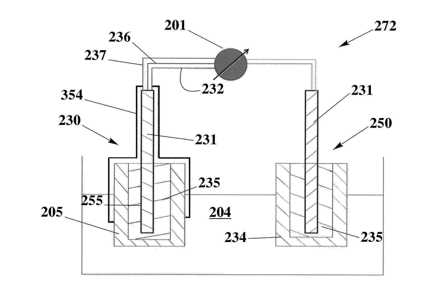
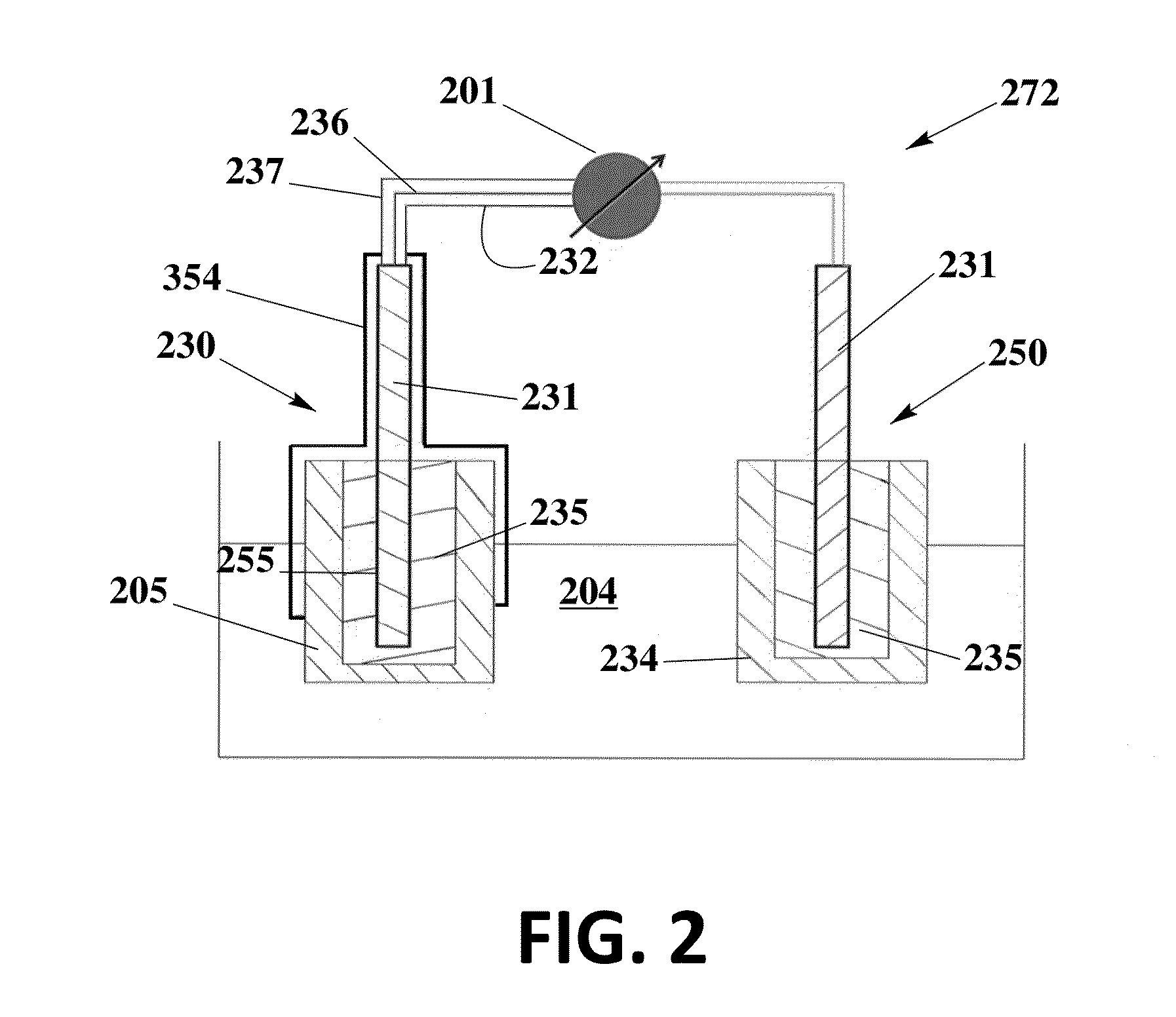
[0083]The solid contact reference electrode 250 is prepared using an ionic liquid for the potential of miniaturization, elimination of liquid junction 301 and dryness of inner electrolyte solutions, and therefore improvement of performance and lifetime.

[0084]To prepare the electrode, a graphite carbon rod (d=7 mm) is inserted into a heatshrink tube to avoid the contact with sample solution and therefore the shortcut. One of its end is soldered with metal wire for the connection to cable. Another end is well-polished and covered with poly(octyl thiophene) (POT) by drop casting its solution (POT is dissolved in chloroform at a concentration of 0.25 mM). After it is dry, new solution is added and this process is repeated for three times. The reference electrode membrane is ortho-nitrophenyl octyl ether (o-NPOE) plasticized poly-(vinyl chloride) (PVC) membrane doped with the ionic liquid 1-methyl-3-octylimidazolium bis(trifluoromethylsulfonyl)-imide (IL). For the best performance, PVC / I...


PUM

PropertyMeasurementUnit
MWaaaaaaaaaa
cure timeaaaaaaaaaa
hydrostatic pressuresaaaaaaaaaa

Abstract

In the present invention, the solid contacted ISE and the solid contacted reference are based on a conductive porous network with a solid contact and membrane disposed thereon. The porous networks are not only mechanically stable, but also provide pore structure for the solid contact and membrane to intercalate, which enhances the life time and stability of the sensors. The invention further incorporates a unique fluidic fitting sensor and sealing mechanism so that measurements can be taken at high pressures. The fitting design has many benefits, such as low cost and disposability, which allows them to be mass manufactured. These sensors can be produced for detection of many different kinds of ions by applying different types of ion selective membranes, including polyvinylchloride (PVC) based ion-selective membranes and fluorous matrixes based ion-selective membranes.

Description

[0001]This application claims the benefit of provisional Patent Application Ser. No. 61 / 725,503 filed on Nov. 13, 2012FEDERALLY SPONSORED RESEARCH[0002]Work relating to this document was supported in part by grants from the National Science Foundation (1113251). The United States government may have certain rights in the subject matter of the invention.FIELD OF THE INVENTION[0003]The present invention relates to devices for quantitatively and selectively measuring ionic analytes.BACKGROUND OF THE INVENTION[0004]Membrane based ISEs have been thoroughly reviewed by Buhlmann (Buhlmann, P., Chen, L. D. Ion-Selective Electrodes with Ionophore-Doped Sensing Membranes” In Supramolecular Chemistry: From Molecules to Nanomaterials; Steed, J. W.; Gale, P. A. Eds.; John Wiley & Sons, Ltd: New York, 2012; Vol. 5, 2539.) which is fully incorporated into this patent by reference. Traditional membrane based ISEs typically incorporate a polymer membrane, an optional plasticizer, a selective element...

Claims


Application Information

Patent Timeline
Patent Type & Authority Applications(United States)
IPC IPC(8): G01N27/333H01B7/00
CPCG01N27/333
Inventor THOMPSON, JONATHANLAI, CHUNZECHEN, LI
Owner UNITED SCI LLC
Why Eureka
Try Eureka