Use of a process for hydrogen production

a technology of hydrogen production and process, applied in the direction of gas-gas reaction process, bulk chemical production, physical/chemical process catalyst, etc., can solve the problems of large financial expenditure, low demand for hydrogen or hythane-operated motor vehicles, and extremely small number of filling stations offering hydrogen

Active Publication Date: 2014-11-06
BESTRONG INT
View PDF19 Cites 20 Cited by
  • Summary
  • Abstract
  • Description
  • Claims
  • Application Information

AI Technical Summary

Benefits of technology

[0028]In accordance with the invention, this is achieved by the use of a method for producing hydrogen, in which at least a portion of a hydrocarbon-containing feed gas is conducted into a reformer, wherein the feed gas is contacted with a catalyst in the reformer, wherein the feed gas is reacted to hydrogen and solid carbon compounds, for the direct (in situ) production of a hydrogen-containing gas at a filling station facility (for consumer supply). Depending on the reaction conditions, the hydrogen-containing gas will constitute pure hydrogen or also mixtures such as, e.g. hythane, still containing a defined portion of unreacted feed gas (e.g. natural gas or methane). According to the invention, a hydrogen-enriched gas is produced in the reformer, which, due to the catalytic decomposition of the feed gas, has a hydrogen content of between 5 and 99.99999 vol % as well as a CO and CO2 content of <1 vol %, and which can be intermediately stored at a filling station facility or even directly distributed to a consumer. By the employed method, hydrogen or even hythane can be produced as a function of the production conditions such as, e.g., the catalyst surface area, gas flow and temperature. If the production of pure hydrogen is desired, gas flows having hydrogen contents of about 80 vol % or more can be directly subjected to further gas cleaning so as to finally obtain pure hydrogen. The advantage of this application resides in that the employed method, in addition to producing hydrogen or hythane, will also produce carbon in the form of carbon black. The carbon thus separated in solid form will, therefore, not be discharged into the environment as the greenhouse gas CO2, but can be eliminated by special techniques.

Problems solved by technology

The number of filling stations offering hydrogen is extremely small and, for the time being, only limited to certain company networks.
Yet, due to a minimum supply infrastructure, also the demand for hydrogen or hythane-operated motor vehicles is accordingly low.
It will only be feasible at considerable financial expenditures to shift this situation in favor of the environmentally friendly hydrogen.

Method used


Image

  • Use of a process for hydrogen production
  • Use of a process for hydrogen production
  • Use of a process for hydrogen production

Examples


example 2

[0130]200 mg of the composite catalyst were loaded into a ceramic boat, which was inserted into a tubular furnace including a hot zone of 30 cm and equipped with a quartz tube of 40 mm diameter and 1000 mm length. The quartz tube was closed on both ends by suitable closures comprising gas supply and gas outlet means.

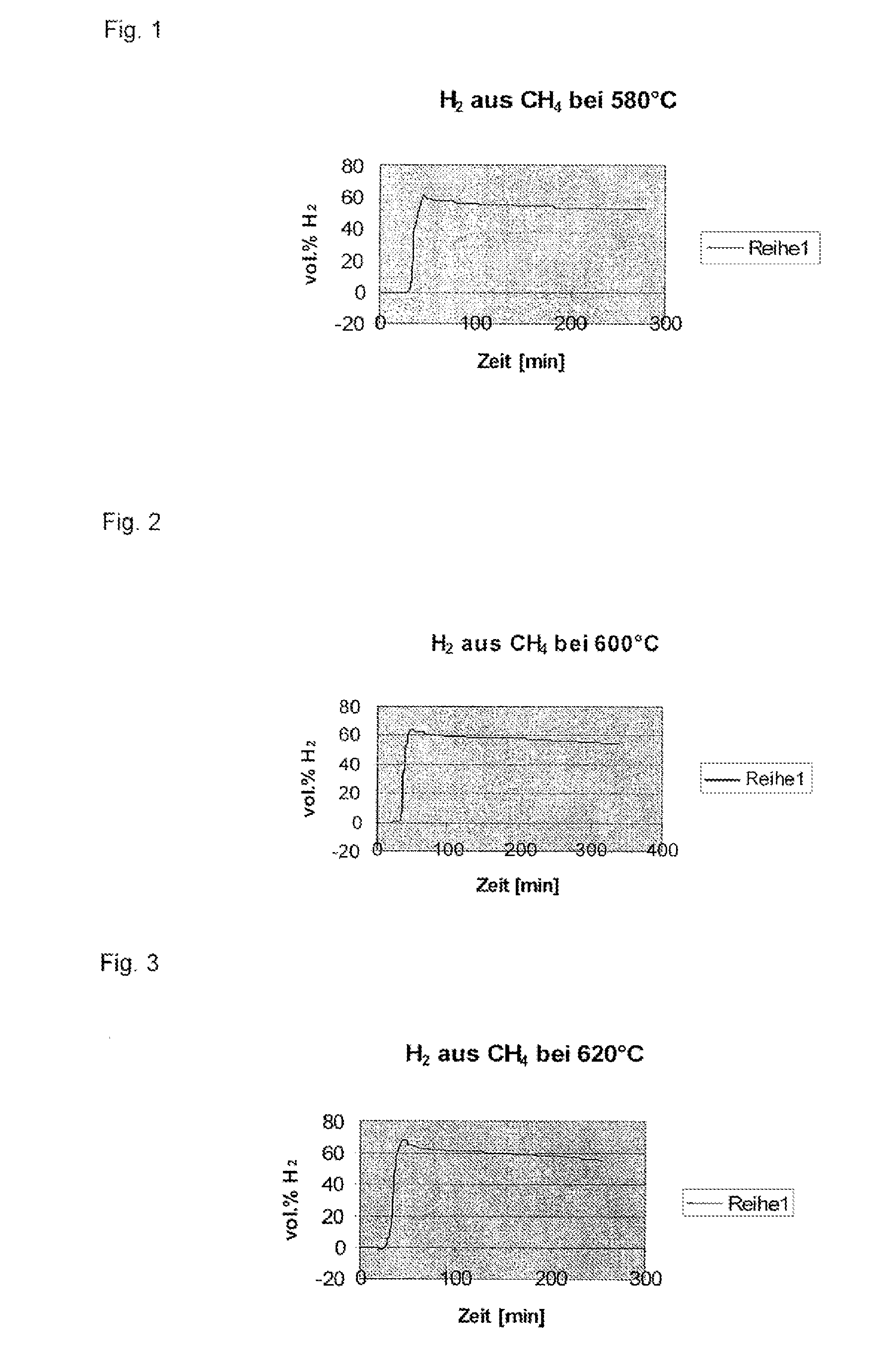
[0131]The whole system was flushed with pure methane. After having started heating to the CVD reaction temperature of 620° C., a methane gas flow of 90 ml / min was adjusted. The heating rate was 10° C. per minute, and a constant temperature of 620° C. was maintained for 4 hours. When reaching a temperature of 350° C., an increase in the hydrogen content was observed in the exhaust gas. After 20 minutes, and having reached of the reaction temperature, a hydrogen concentration of 68 vol % was measured in the exhaust gas. During the four-hour test period, the hydrogen concentration dropped continuously, still amounting to 51 vol % at the end. After cooling to room temperatur...

example 3

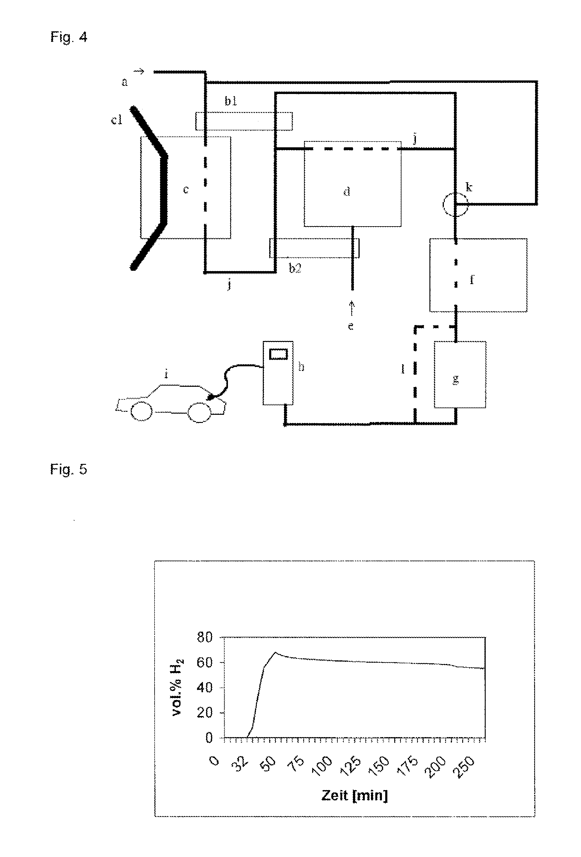
[0133]A filling station facility according to the present invention will now be explained in more detail with reference to FIG. 4. This schematic illustration depicts an inlet for a hydrocarbon-containing feed gas (a) into a reformer (c). In the reformer, the feed gas is reacted to hydrogen on a catalyst under reaction conditions. In the present embodiment, the reformer (c) comprises a supply and discharge device (cl) for the continuous supply and discharge of the catalyst. The hydrogen-containing exhaust gas of the reformer is facultatively conducted, via an exhaust gas line (j) that is suitable for the transport of hydrogen, i.e. sufficiently tight, both directly and through a steam reformer (d), via a mixing device (k), into a compressor or a cooling device (f). The feed gas injected into the reformer is preferably preheated via a heat exchanger (b1) by the exhaust gas (j) from the reformer, or from the steam reformer. The steam reformer is equipped with a steam inlet (e). The st...

example 4

Batch Tests

[0134]The catalyst (about 200 mg) was loosely poured on ceramic base platelets, inserted in an electrically heated, horizontal tube (4 cm diameter) via its front end, and heated. The surface area covered by the solid was about 5×1 cm.

[0135]CH4 at ambient temperature was continuously introduced through several end-side openings at a clear-tube speed in the hot section of about 4 mm / s, and the H2 / CH4 mixture forming was continuously discharged. The hydrogen concentration was measured and the reaction was stopped after the concentration had dropped to about 57 vol. %. Reaction time: about 3.5 hours.

[0136]After the reaction and cooling of the tube, the ceramic supports covered with carbon fiber removed again.

[0137]Reaction pressure: pressureless to slight overpressure (<100 mbar)

[0138]Reaction temperature: 620° C.

[0139]Conversion rate (produced mol H2 / used mol CH4): about 60% Gas residence time in the reactor (reactor volume above catalyst / natural gas flow): 12.8 s

[0140]Speci...


PUM

PropertyMeasurementUnit
temperaturesaaaaaaaaaa
operating temperaturesaaaaaaaaaa

Abstract

The present invention relates to the use of a process for hydrogen production in which at least a part of a hydrocarbonaceous feed gas (a) is passed into a reformer (c), wherein the feed gas is contacted in the reformer with a catalyst and the feed gas is converted to hydrogen and solid carbon, for the direct production of a hydrogenous gas at filling stations for sale to a consumer, and also to a reactor (d) for hydrogen production.

Description

CROSS REFERENCE FOR RELATED APPLICATION[0001]This application is divided from U.S. patent application Ser. No. 12 / 092,231 derived from International Application No. PCT / AT06 / 00441 filed on Oct. 27, 2006, content of which is incorporated herein in its entirety.FIELD OF THE INVENTION[0002]The present invention relates to the field of hydrogen production and its distribution infrastructure.BACKGROUND OF THE INVENTION[0003]There has been great interest in hydrogen as an energy carrier in the transport sector. Hydrogen is perceived as environmentally friendly, in particular, because no CO2 emissions are caused at its combustion by the end consumer. This view, however, ignores that greenhouse gas emissions are caused during its production and supply. Since energy losses occur at every energy conversion, the hydrogen supply infrastructure is, at present, relatively inefficient due to its complexity. This constitutes an essential disadvantage, in particular, in the spreading of hydrogen tec...

Claims


Application Information

Patent Timeline
Patent Type & Authority Applications(United States)
IPC IPC(8): C01B3/26B01J12/00
CPCC01B3/26B01J12/005C01B2203/0277C01B2203/1052C01B2203/1082C01B2203/0833B01J23/755B01J23/882B01J37/033B01J37/035B01J2523/00B82Y30/00B82Y40/00C01B3/28C01B3/382C01B2203/0233C01B2203/043C01B2203/044C01B2203/047C01B2203/085C01B2203/1047C01B2203/1241C01B2203/142C01B32/16C01B32/18Y02P20/129Y02P20/52B01J2523/22B01J2523/68B01J2523/845
Inventor HAMMEL, ERNSTMAUTHNER, KLAUS-DIETERBRICETA, WALTER
Owner BESTRONG INT
Why Eureka
Try Eureka