Gas-fed fermentation systems

a fermentation system and gas-fed technology, applied in the field of fermentation systems, can solve the problems of insufficient global available farm land to meet the increasing needs of both food and fuel, high production cost, and insufficient amount of biofuel generated to date, and achieve the effects of efficient heat exchange and waste gas removal, efficient mass transfer of gaseous substrates, and efficient heat exchang

Active Publication Date: 2015-09-17
CALYSTA
View PDF12 Cites 12 Cited by
  • Summary
  • Abstract
  • Description
  • Claims
  • Application Information

AI Technical Summary

Benefits of technology

[0014]In one aspect, the present disclosure provides a method and apparatus for efficient mass transfer of gaseous substrates for microbial fermentation. Additionally, this disclosure provides a method for fermenting gaseous carbon-containing feedstocks using a culture primarily comprising a C1 metabolizing non-photosynthetic microorganism. In yet another aspect, this disclosure provides a scalable fermentor design for allowing high flux gas-phase to liquid-phase mass transfer in addition to efficient heat exchange and waste gas removal. Systems and methods for fermentation that overcome disadvantages known in the art and provide the public with new methods for the optimal production of a variety of products are provided.

Problems solved by technology

But, biofuels generated to date have their own difficulties and concerns.
The amount of globally available farm land is insufficient to satisfy the increasing needs for both food and fuel.
But, technical difficulties in production, along with the high cost of production, have not made second generation biofuels any more cost-effective or accessible.
Historically, methane has been viewed as a somewhat valuable byproduct that is difficult to convert to higher value products or to transport to the marketplace from remote or stranded locations such as remote gas fields or off-shore production platforms.
But, methane's volatility makes the transport and / or direct usage of methane as a fuel problematic.
The F-T process yields petroleum products consistent with today's fuel supply, but suffers from a number of drawbacks, including low yields, poor selectivity (making downstream utilization complex), and requires significant capital expenditure and scale to achieve economical production (Spath and Dayton, December 2003 NRELITP-510-34929).
The massive scale required for an F-T plant (generally in excess of two billion dollars in capital cost [Patel, 2005]) also represents a significant limitation due to the large amount of methane feedstock required to offset the enormous capital cost of the F-T process.
As methane transportation is prohibitively expensive in most cases, such a plant must be co-located with a steady, reliable, and cost efficient source of methane, usually in the form of a significant methane reservoir or a methane pipeline.
An additional cost and scaling factor is the economics of gas-scrubbing technologies (Spath and Dayton, 2003), since F-T catalysts are quite sensitive to common contaminants found in natural gas that pass unaffected through the syngas conversion process.
The requirements for ready access to large volumes of a relatively clean methane containing gas, combined with a massive capital investment, currently limit natural gas based F-T plants to successful and economically viable operation in only a few locations world-wide (Spath and Dayton, 2003).
The high minimum processing requirement for a gas-to-liquids process or liquified natural gas plant, combined with the high cost of transport, result in smaller methane sources remaining as ‘stranded’ gas deposits.
Due to the current absence of efficient small-scale conversion technologies, such stranded gas sources are typically vented to atmosphere or flared, as methane accumulation presents a significant safety risk.
However, despite significant research and development over the last 70+ years, the limitations of Fischer-Tropsch technology prevent broad adoption of commercial gas-to-liquids processes.
However, fermentation of gaseous substrates such as methane, CO, or CO2 presents significant challenges due to the requirement that the carbon substrate must be transferred from the gas phase to an aqueous phase to allow for uptake and metabolism by the C1 metabolizing non-photosynthetic microorganisms in culture.
The surface area between the gas and liquid phases in most fermentation systems is primarily limited by the bubble size of the input gas.
The stirrer blades generate turbulence and shear in the liquid while gas bubbles are introduced at the bottom of the fermentor, thus impeding the progress of the bubbles as they travel up the fermentor and shearing the gas bubbles to reduce the tendency of the bubbles to coalesce within the fermentor.
However, this type of fermentor can be difficult to scale-up, as the energy requirements to obtain the same rate of mixing and mass transport can be prohibitive as the volume increases.
Further, the vigorous mixing implies a significant heating of the fermentation liquid, and the use of a single large fermentor limits the surface area available for heat exchange cooling.
Flow rates and shear forces in airlift fermentors are significantly lower than in stirred tank fermentors, which also tend to increase bubble coalescence and reduce the efficiency of cooling the fermentor.
Finally, separation of the unused and waste gases from the mixture exiting the upflow portion of the fermentor prior to the return of the liquid to the downflow section can be challenging.

Method used


Image

  • Gas-fed fermentation systems
  • Gas-fed fermentation systems
  • Gas-fed fermentation systems

Examples


Embodiment Construction

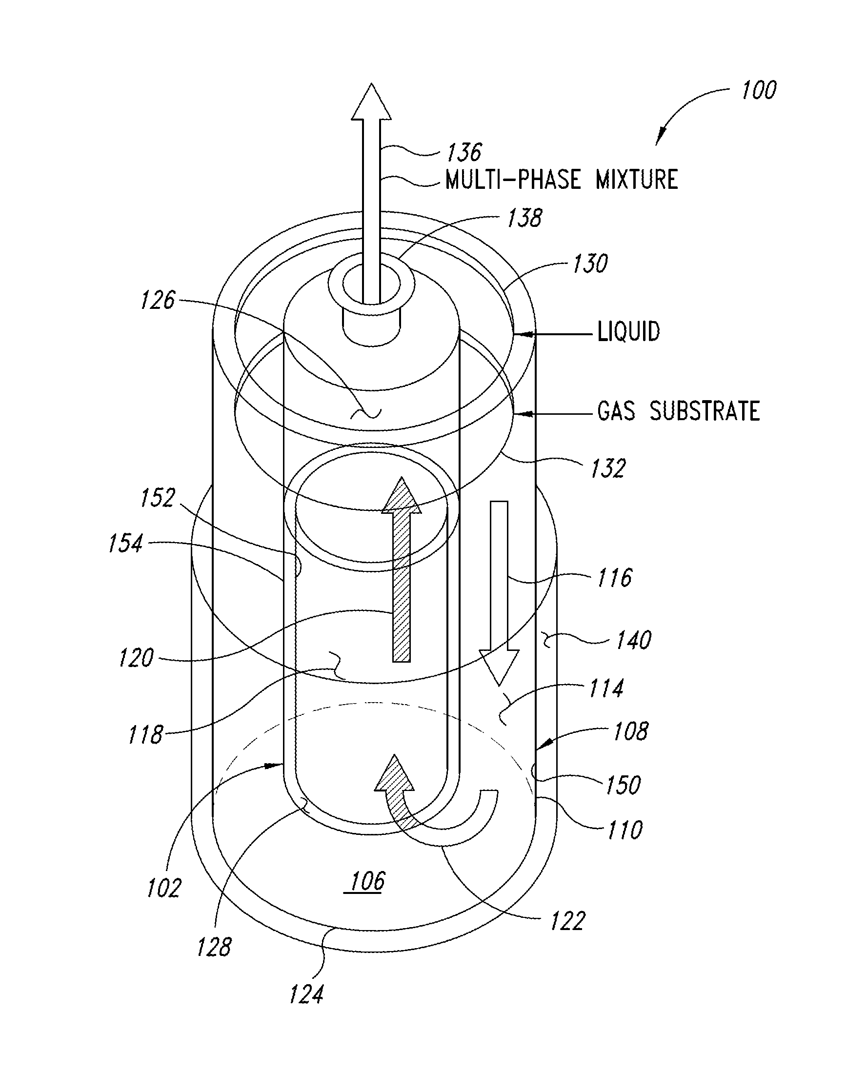
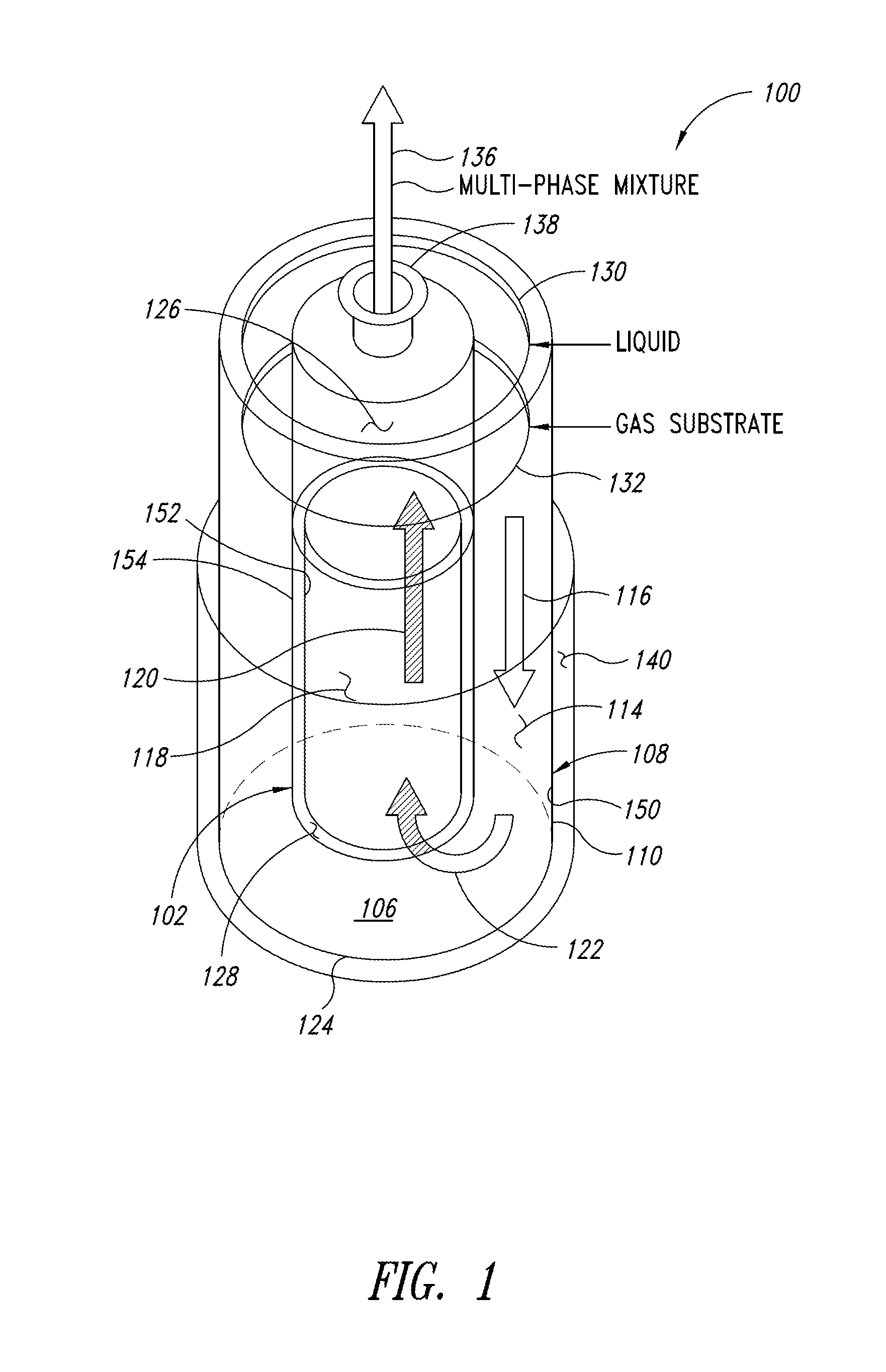
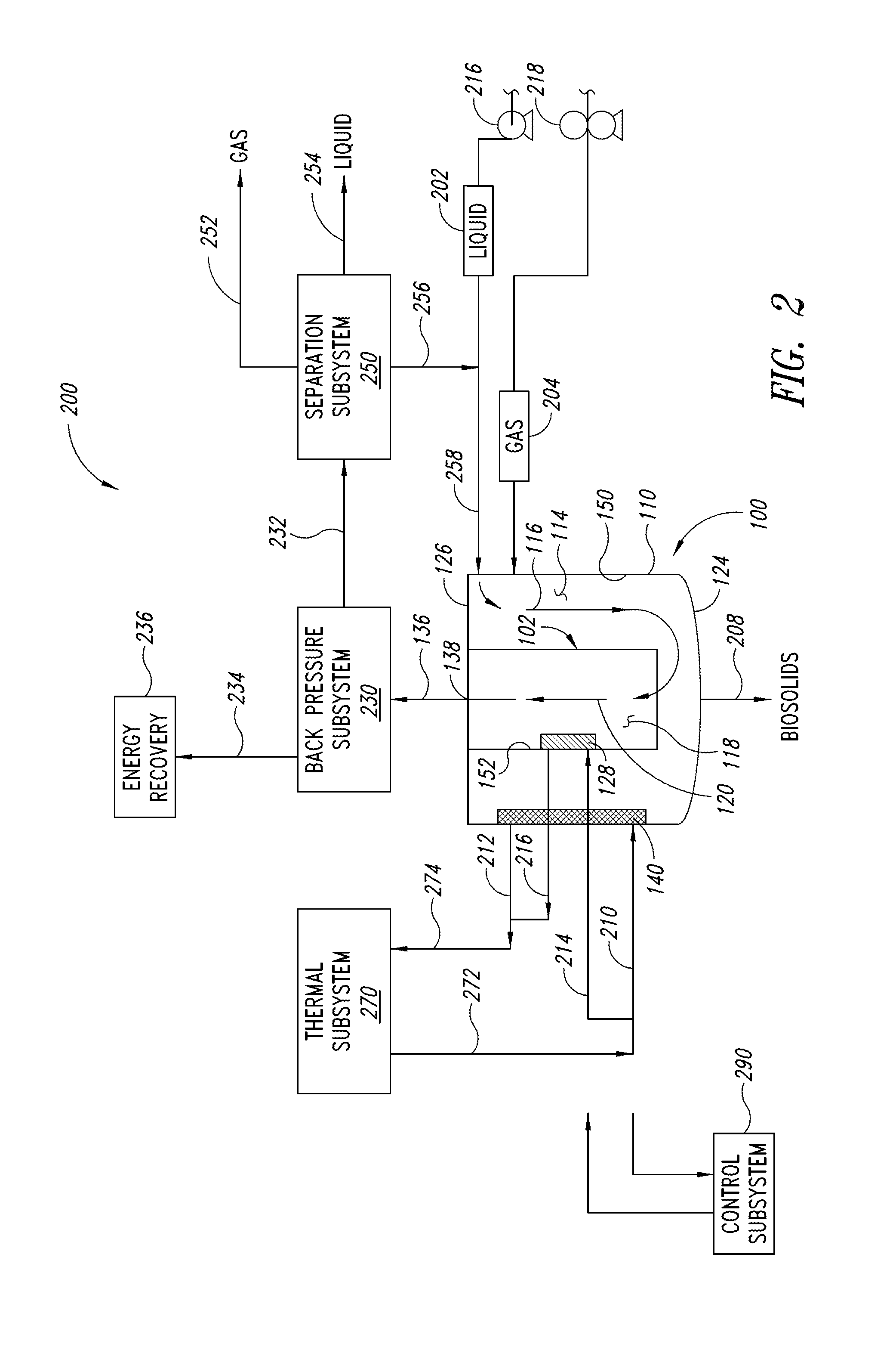
[0029]In the following description, certain specific details are set forth in order to provide a thorough understanding of various embodiments. However, one skilled in the art will understand that the invention may be practiced without these details. In other instances, structures, standard vessel design details, detailed design parameters of available components such as liquid or gas distributors, pumps, turbines, and similar, details concerning the design and construction of American Society of Mechanical Engineers (ASME) pressure vessels, control system theory, specific steps in one or more fermentation processes, and the like have not been shown or described in detail to avoid unnecessarily obscuring descriptions of the embodiments. Unless the context requires otherwise, throughout the specification and claims which follow, the word “comprise” and variations thereof, such as, “comprises” and “comprising” are to be construed in an open, inclusive sense, that is, as “including, bu...


PUM

PropertyMeasurementUnit
pressureaaaaaaaaaa
pressureaaaaaaaaaa
velocityaaaaaaaaaa

Abstract

A fermenter can have at least one hollow fluid conduit disposed at least partially within a vessel. An external circumference of the hollow fluid conduit and an interior circumference of the vessel can define a downward flow path through which a multi-phase mixture including a liquid media and compressed gas substrate bubbles flows. An interior circumference of the hollow fluid conduit can defined an upward flow path which is in fluid communication with the downward flow path. The multi-phase liquid can flow through the upward flow path and exit the fermenter. Cooling may be provided in the hollow fluid conduit or the vessel. One or more backpressor generators can be used to maintain a backpressure on the fermenter. One or more fluid movers can be used to variously create an induced and/or forced flow in the downward and upward flow paths.

Description

BACKGROUND[0001]1. Technical Field[0002]This invention is generally related to vessels, systems and processes useful in fermentation and, in particular, fermentation systems using a gaseous substrate.[0003]2. Description of the Related Art[0004]With the ever increasing depletion of fossil fuel deposits, the increasing production of greenhouse gases and recent concerns about climate change, substituting biofuels (e.g., ethanol, biodiesel) for fossil fuels has become an industrial focus. But, biofuels generated to date have their own difficulties and concerns. First generation biofuels are derived from plants (e.g., starch; cane sugar; and corn, rapeseed, soybean, palm, and other vegetable oils), but these fuel crops compete with crops grown for human and animal consumption. The amount of globally available farm land is insufficient to satisfy the increasing needs for both food and fuel. To reduce the demand placed upon food producers for biofuel compatible grains, second generation b...

Claims


Application Information

Patent Timeline
Patent Type & Authority Applications(United States)
IPC IPC(8): C12M1/00C12P17/02C12M1/12C12P7/16C12P7/42C12P7/40C12P5/02C12P7/18
CPCC12M29/08C12P5/02C12P17/02C12M23/06C12P7/16C12P7/42C12P7/40C12P7/18C12M23/34C12M29/06C12M41/24Y02P20/582C12M27/24Y02W10/30C12M1/02C12M1/04C12M1/08Y02E50/30
Inventor SILVERMAN, JOSHUA A.RESNICK, SOL M.REGITSKY, DREW D.
Owner CALYSTA
Why Eureka
Try Eureka