

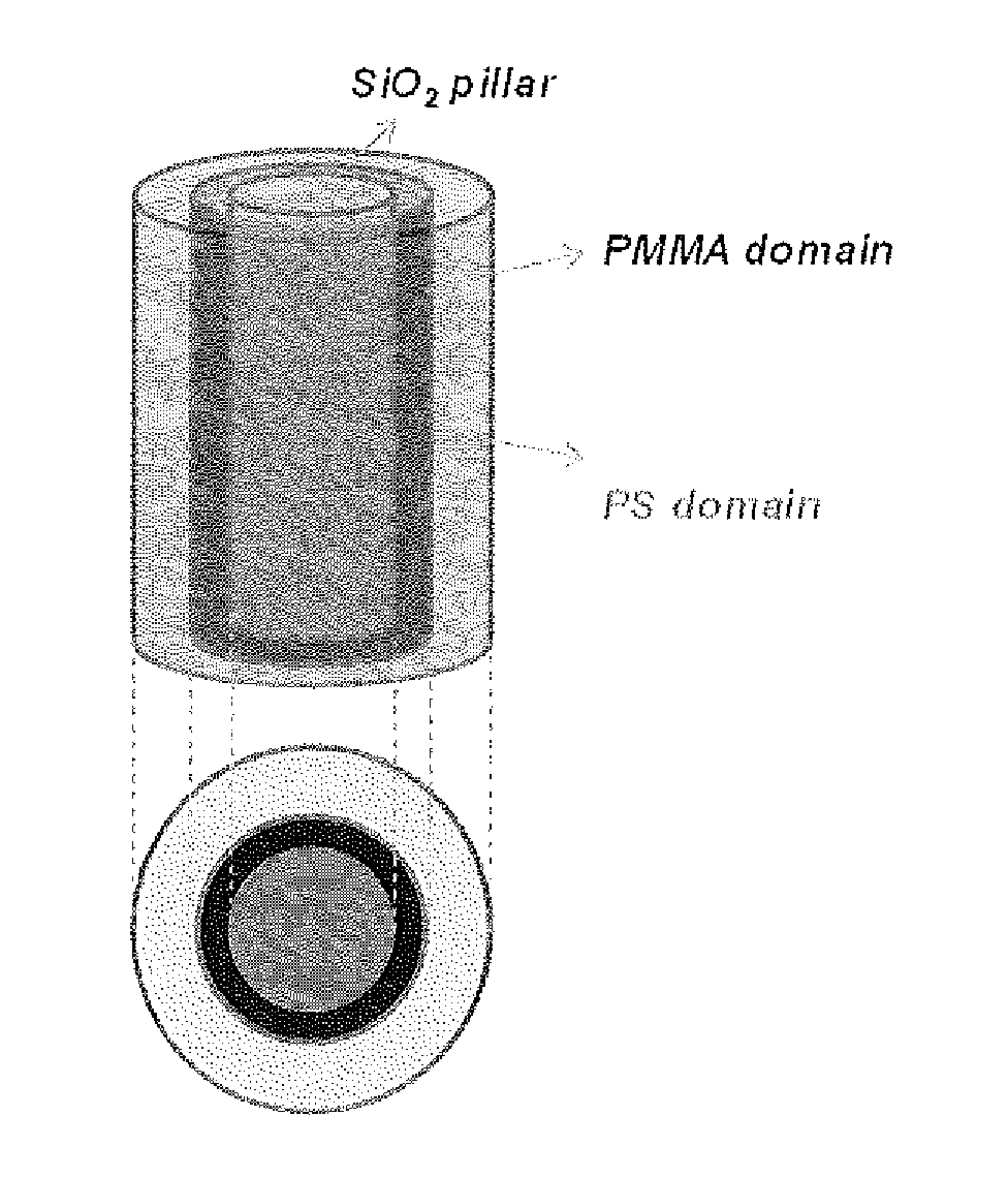
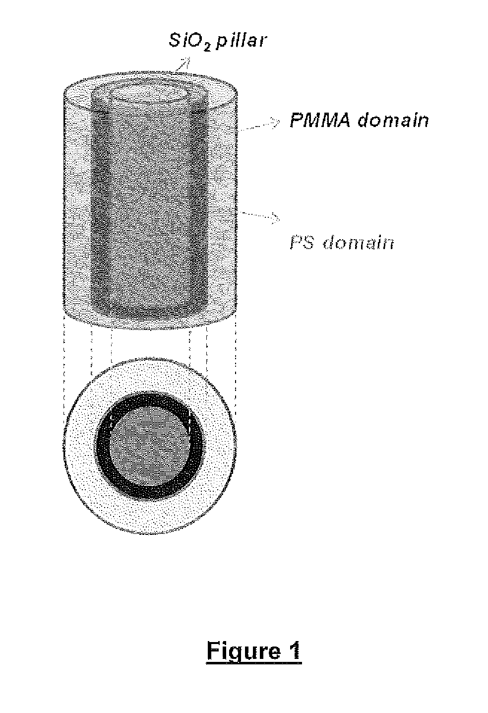
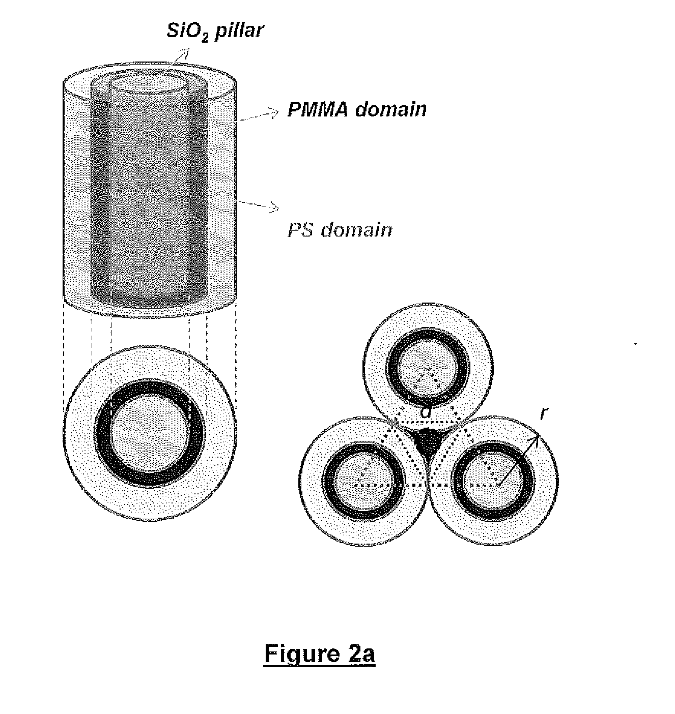
Defect reduction methods and composition for via formation in directed self-assembly patterning
a technology of defect reduction and composition, applied in the direction of film/foil adhesives, microstructure devices, coatings, etc., can solve the problems of difficult to achieve further reduction of pattern dimensions, limited integrated circuit feature dimensions, and less radiation-exposed regions
- Summary
- Abstract
- Description
- Claims
- Application Information
AI Technical Summary
Benefits of technology
Problems solved by technology
Method used
Image

Examples
synthesis example 1
Synthesis of Azo Initiator with Phosphonate Pendant Groups
[0104](1) 4,4′-Azobis(4-cyanopentanoyl chloride) as an isomer mixture: All procedures were conducted under nitrogen atmosphere. A suspension of 70 g of PCl5 in about 240 ml of dichloromethane was prepared in a round bottom flask with a mechanical stirrer. To this suspension, 9.1 g of 4,4′-azobis(4-cyanovaleric acid) were added by portions within 25 minutes. The mixture was stirred for 2 hours at 0-2° C., then 40 hours while it warmed up to 16° C. The excess solid of phosphorus pentachioride was filtered off, washed with CH2Cl2 (2×10 ml). The resultant solution was concentrated using rotary evaporator at room temperature to give 115 g of colorless liquid. The material was then placed in a freezer at −20° C. for 4 hours. The cold solution was decanted into 200 ml of hexane with good stirring and a colorless solid was filtered and well washed with hexane. Yield: 7.3 g (70.8%); m.p. 75-77′C; 1H NMR (CDCl3, δ ppm) 1.68 (s) and 1.7...
synthesis example 2
Synthesis of Polystyrene Brush Precursor with Phosphonate End Group
[0107]In a 250 nil flask equipped with a magnetic stirrer, water condenser and gas bubbler a solution was made consisting of 1.7234 g (1.84 mmol) of the azo initiator prepared in above example 1 (3), 44.779 g (0.43 mol) of styrene dissolved in 60 ml of 2-butanone. Nitrogen gas was bubbled through the solution for 45 minutes, and while stirring the mixture was heated to 80° C. for 15.5 hours. The reaction mixture was cooled to room temperature and the solution was poured slowly into 1.8 L of MeOH under stirring. The polymer was isolated by filtration, dried (60° C.) and purified through reprecipitation from 95 ml of THF solution into 1.3 L of methanol, washed with methanol and dried at 60° C. in a vacuum oven until constant weight of 20.4 g, yield: 43.9%. Mn 23086 g / mol; Mw 40616 g / mol; PD 1.76. 1H NMR (CDCl3, δ ppm): 3.58-3.4 (m, —CH2—N), 4.18-3.98 (m, CH3—CH2—O—P);
synthesis example 3
Synthesis of Azo Initiator with Hydroxy Pendant Groups
[0108](1) A solution of tetramethylammonium pentahydrate was prepared by dissolving 63 g of this material in (0.348 mole) 100 g of methanol. This solution was slowly added to a solution of 48.72 g (0.174 moles) of 4,4′-azobis(4-cyanovaleric acid) suspended in 100 g of methanol with stirring at a rate of addition such that the temperature of the reaction did not rise above 40° C. After the addition was complete the reaction mixture was stirred for an additional hour. After this time the reaction mixture was mostly stripped of methanol under with a rotary evaporator at room temperature. This concentrated reaction mixture was then poured into a flask containing diethyl ether thereby precipitating an oily layer at the bottom of the flask. The supernatant ether was then poured off and the oily residue retained. Into the flask containing the oily residue more diethyl ether was added with stirring to wash the residue. This was repeated ...
PUM
| Property | Measurement | Unit |
|---|---|---|
| contact angle | aaaaa | aaaaa |
| contact angle | aaaaa | aaaaa |
| polydispersity | aaaaa | aaaaa |
Abstract
Description
Claims
Application Information