Proximal degas driven microfluidic actuation

a microfluidic and actuation device technology, applied in the direction of positive displacement liquid engine, laboratory glassware, instruments, etc., can solve the problems of inability to inability to use control and complicated flow patterns, and inability to achieve controlled and complicated flow patterns. , to achieve the effect of reducing the number of dead-volume in the pumping apparatus, reducing the oscillation of fluid flow velocity, and eliminating any dead-volume within the pumping apparatus

Active Publication Date: 2016-05-26
RGT UNIV OF CALIFORNIA
View PDF8 Cites 14 Cited by
  • Summary
  • Abstract
  • Description
  • Claims
  • Application Information

AI Technical Summary

Benefits of technology

[0019]Embodiments of the apparatus generally include three main components: 1) the proximal degas / vacuum channels, 2) the fluidic network, and 3) a means for removing air from the degas / vacuum channels. The fluidic channel and the degas channel networks are located in close proximity to each other but are isolated, separated by gas porous walls. The selectively permeable walls allow gases to pass through while restricting access to the aqueous sample or carrier liquids due to the low surface energy of the porous material. The Proximal Degas-driven Flow (PDF) methods take advantage of the high porosity and air solubility of materials such as PDMS, TPX (polymethylpentene), silicone, rubber, etc. to reduce the pressure inside microfluidic channels using proximal degas vacuum lines, which leads to fluidic actuation within the microfluidic channels.
[0022]In use, the input ports for the fluidic channels are loaded with a sample solution and the surrounding proximal degas channels, which are connected to a negative pressure source are partially or fully evacuated. Air within the fluidic channel diffuses out through the porous walls, due to the high air permeability and solubility of the walls, and into the nearby degas channels under the pressure gradient created across the barrier walls. This degassing process leads to a reduction in the fluidic channel pressure and results in the liquid solution flowing into the fluidic channels from the inlet port that is at atmospheric pressure. Air evacuation from the fluidic channel leads to continuous fluid flow into the fluidic channel until either the fluidic channel is completely loaded or a pressure equilibrium is reached. The principle behind this technique allows inherently bubble-free liquid actuation and eliminates any dead-volume within the pumping apparatus. This method also provides microfluidic pumping, without any auxiliary equipment or device pre-treatment, and can fill dead-end channels and chambers.
[0023]Since the sample solution is isolated from the pumping apparatus, and is impermeable to the diffusion barrier walls, the system can be used for integrated molecular diagnostics, multiplexing and for pumping biohazardous fluids. For example, the technique is ideal for handling biohazardous fluids avoiding the need for sterilizing the actuators after each run since the fluid sample never comes into contact with any of the pumping machinery. Additionally, the isolation of the fluid sample from the integrated pressure source minimizes oscillations in fluid flow velocity and generates average flow velocities in the range of 0.7 to 8 mm / s in the preferred embodiments of the apparatus.
[0024]The effect of different device design parameters on fluid flow with proximal degas flow was also characterized. These parameters included the distance between the proximal degas channels and the fluid network channels (referred to as the proximity), fluid channel geometry, the chamber diameter, and the membrane thickness of the thumb-pump. The simulations suggested that the fluid loading performance could be tuned by varying these parameters, thus achieving a wide range of flow velocities and degas pressures. Experimental results confirmed the simulation models and the capacity for rapid and bubble-free fluid actuation was also demonstrated.
[0025]Accordingly, a wide variety of portable microfluidic platforms and diagnostic devices can be designed that can be actuated at the point of care without the need for large, expensive and power consuming pumping systems. The device design can also be tuned to achieve a range of flow velocities from this technique and can be operated on demand by using a convenient finger pump. Also, these devices do not require any prior degassing or priming alleviating any need for special device packaging, greatly reducing the cost of the consumable device.

Problems solved by technology

However, very few of the advancements in microfluidic technology have been successfully commercialized into functional and practical products for point-of-care testing and on-site environmental monitoring.
An essential challenge in accomplishing functional microfluidic devices is the need for reliable fluidic actuation for bubble-free, reliable, stand-alone, autonomous loading of fluids.
Although many fluidic actuation schemes have been developed for microfluidic devices, most of these methods are either excessively complex, dependent on external power sources eliminating mobility, or are overly simplified and not amenable to the controlled and complicated flow patterns required for the integration of advanced biomolecular assay techniques.
However, both types of fluidic actuation techniques have systemic limitations.
However, pressure-driven actuation often requires burdensome or expensive external equipment and the scheme is vulnerable to bubble formation that can create large dead volumes as well as oscillatory flow.
Additionally, these active pumping mechanisms are generally not suitable for filling up dead-end structures that are attractive for complex quantitative, digitized and multiplexed assays.
The same problems are encountered with the electrokinetic-driven flow, which requires a high voltage (50 V to 1000 V) to be exerted on the integrated electrodes to transport the liquid.
This high voltage requirement makes it difficult to miniaturize without off-chip power supplies, and the flow control is not easy due to the variability in material surface properties and the vulnerability of fluid properties.
Additionally, air bubbles and heat can develop in electrokinetic flow systems, interfering with liquid manipulation and system operation.
Although these active fluid actuation methods have advantages that make them desirable in some applications, their characteristics restrict their utility in applications where portability is essential, thus use beyond the research laboratory has been limited.
However, this method is only used in non-complex, low accuracy applications because it lacks controllability and repeatability in humid settings.
Gravity-driven flow is based on the physical existence of gravity but the devices need pre-priming and sometimes the surface tension dominates in the miniaturized devices leading to inconsistent flows.
For the pumping based on surface tension, such as evaporation-induced and droplet-based driven flow, the vulnerability to environmental conditions (temperature, humidity etc.) restricts them to applications and uses at locations that have controlled atmospheric conditions that do not vary during the operation process.
Although passive devices are portable and disposable, these passive actuation techniques often lack tunability, reproducibility and require meticulous device pre-treatment or storage, which limit their employment in devices requiring accuracy and reliability.
Apart from causing problems with air bubble formation, fluid instabilities, dead volumes and inter-device repeatability, direct exposure of biofluids to the actuation apparatus raises concerns about biosafety especially when dealing with biohazardous fluids.

Method used


Image

  • Proximal degas driven microfluidic actuation
  • Proximal degas driven microfluidic actuation
  • Proximal degas driven microfluidic actuation

Examples


example 1

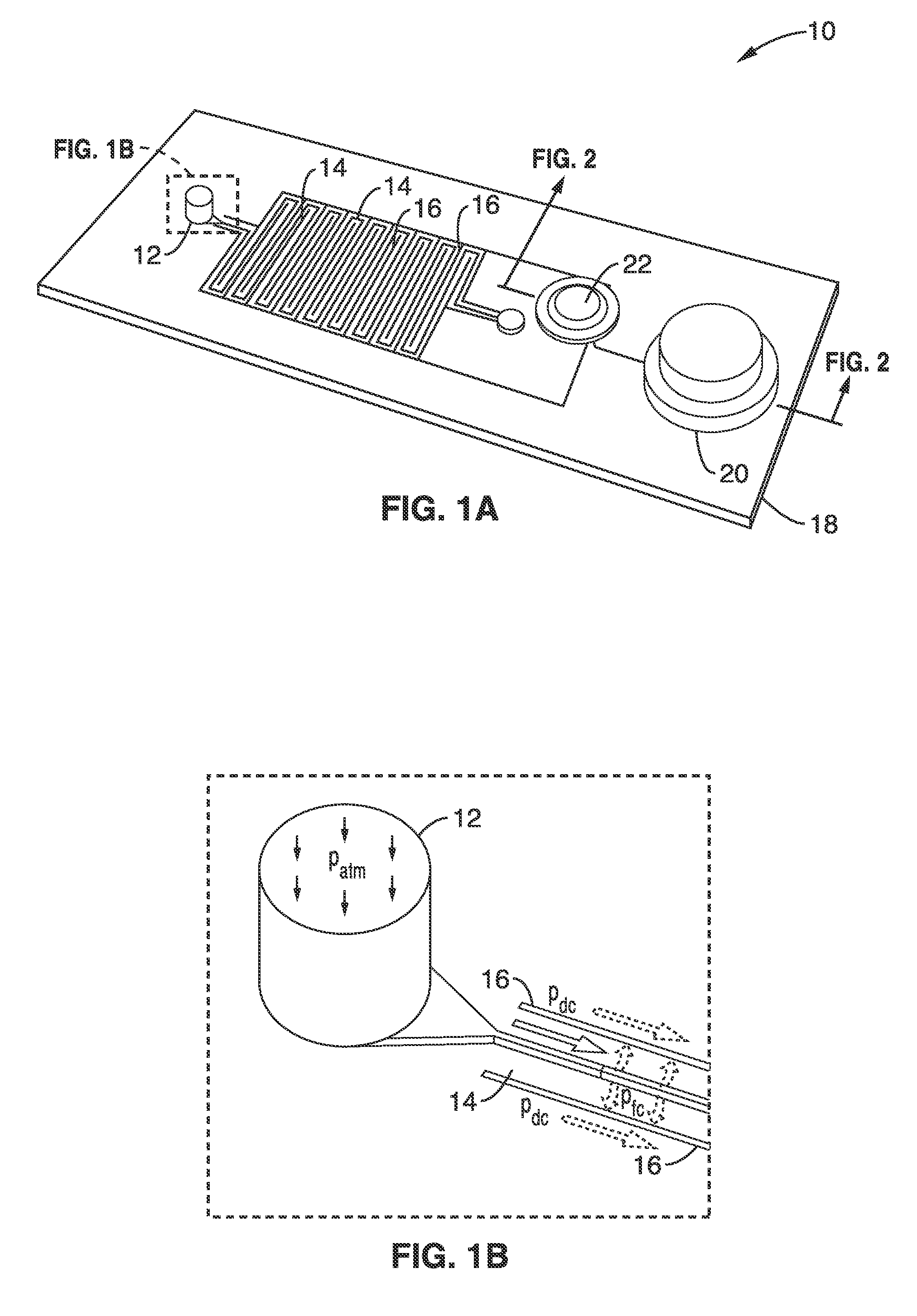
[0083]In order to demonstrate the operational principles of the apparatus and methods, simulations were performed to validate the theoretical models, and to understand the effect of various design parameters on fluid actuation and to determine the specific correlations between the key parameters. Two different types of simulations were performed: 1) an investigation into how different parameters influence fluid flow assuming constant pressure in the degassing channel network; and 2) an analysis of different thumb-pump parameters for the comparison of pressures obtainable within the degas channel network using the schematic structure shown in FIG. 5.

[0084]Based on the theoretical model using the schematic structure shown in FIG. 4, the three main parameters that were varied for the characterization study were the barrier thickness d, the fluidic channel width w, and the applied negative pressure in the degas channel network Pd. For the simulations, the total fluidic channel length wa...

example 2

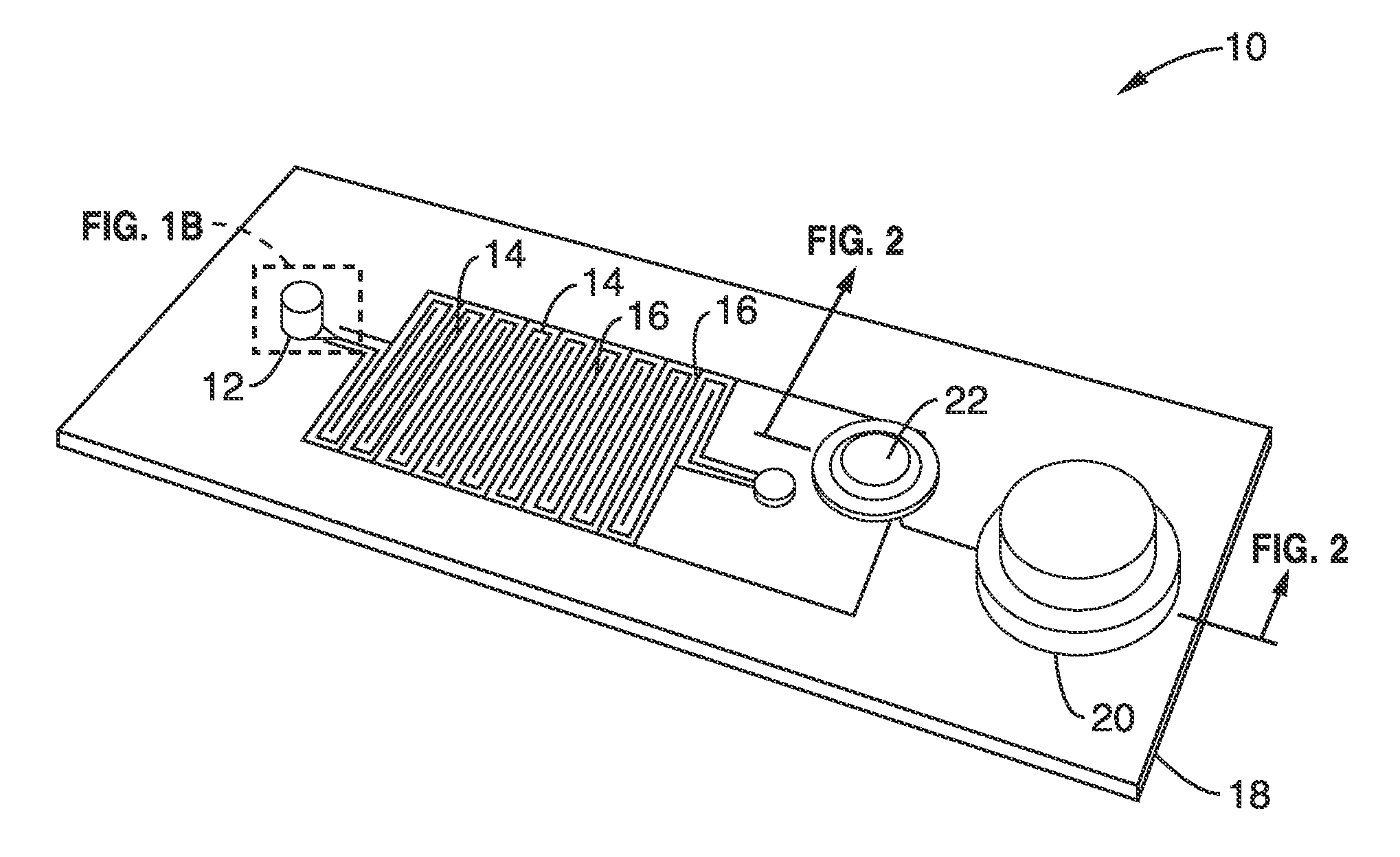
[0096]Many options exist for the source of reduced pressure which can be used for the device. For the initial characterizations a vacuum pump (with a bleed valve) was used to apply a measured and controlled vacuum pressure. This technique is ill suited for point of care testing applications and therefore a standalone device using an integrated membrane thumb-pump as the vacuum source was designed and simulated.

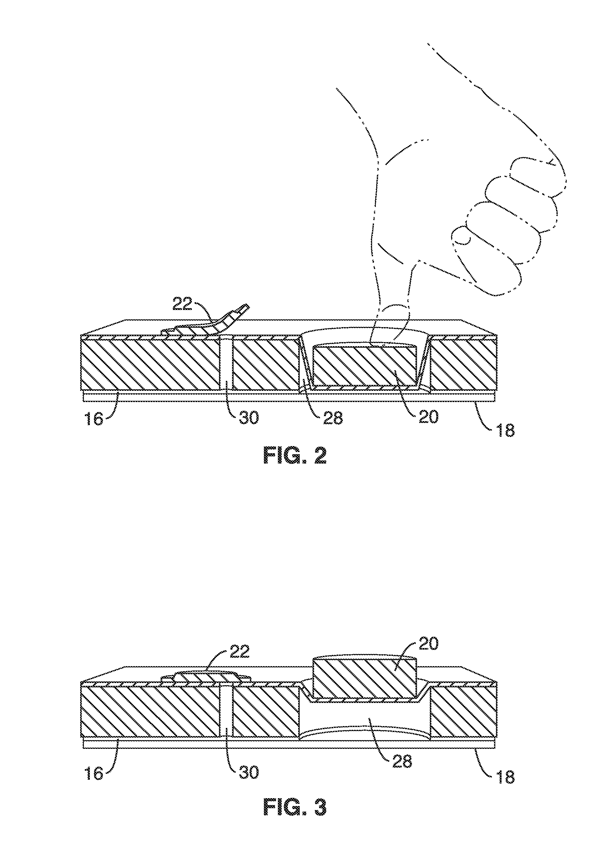
[0097]Simulations were performed that coupled fluidic actuation with an integrated on-chip finger operated membrane pump as shown schematically in FIG. 1C and FIG. 3. The membrane deflection pushes air out of a one-way air valve and its subsequent relaxation pulls out air from the degas lines generating a vacuum in the channels.

[0098]The diameter of thumb-pump chamber and the thickness of the silicone membrane were two parameters that were varied for the integrated thumb-pump structure simulations. The simulated thumb-pump chamber height was 4 mm, membrane thickness was 0.81 m...

example 3

[0100]The experimental validation of the simulations of Example 1 was done by the simultaneous measurement of pressure and fluid momentum in a dead end channel. Devices were fabricated using standard soft lithography processes. Multiple parameters were considered such as the distance between the degas channel network and the fluidic channel network (i.e. proximity), the channel width, and the relative vacuum pressure in the degas channel network. Thumb-pump simulations were also validated experimentally.

[0101]Devices with structures with different barrier layer thicknesses, channel widths and channel lengths were fabricated. To produce a device structure, a SU-8 (MicroChem Corp.) mold was first fabricated on a silicon wafer using contact photolithography. The requisite height of 30 μm was obtained with a tolerance of around 10%. The mold was then hard baked and silanized using Trichloro(1H,1H,2H,2H-perfluorooctyl)silane (Sigma Aldrich). The PDMS (Dow Corning Corp.) base and curing a...


PUM


Abstract

An apparatus with a self-contained, tunable, microfluidic pumping system that utilizes the high air permeability of the matrix material to actuate fluid flow in a network of fluidic microchannels and microstructures is provided. The pumping relies upon partial evacuation of degas / vacuum channels that are located next to the fluid channels to degas air from the fluid channels or structures producing a reduction of pressure in the fluidic channel leading to the flow of fluid from an inlet at atmospheric pressure through the device. The solution is isolated from the pumping apparatus since the liquid does not pass through the diffusion barriers. The apparatus and method can also provide bubble-free microfluidic pumping, without any auxiliary equipment or device pre-treatment, and can fill dead-end channels and chambers, providing a powerful liquid handling tool for a broad range of applications.

Description

CROSS-REFERENCE TO RELATED APPLICATIONS[0001]This application is a 35 U.S.C. §111(a) continuation of PCT international application number PCT / US2014 / 039333 filed on May 23, 2014, incorporated herein by reference in its entirety, which claims priority to, and the benefit of, U.S. provisional patent application Ser. No. 61 / 826,982 filed on May 23, 2013, incorporated herein by reference in its entirety. Priority is claimed to each of the foregoing applications.[0002]The above-referenced PCT international application was published as PCT International Publication No. WO 2014 / 190258 on Nov. 27, 2014, which publication is incorporated herein by reference in its entirety.STATEMENT REGARDING FEDERALLY SPONSORED RESEARCH OR DEVELOPMENT[0003]Not ApplicableINCORPORATION-BY-REFERENCE OF MATERIAL SUBMITTED IN A COMPUTER PROGRAM APPENDIX[0004]Not ApplicableBACKGROUND[0005]1. Field of the Disclosure[0006]This disclosure pertains generally to microfluidic devices and pumping schemes, and more parti...

Claims


Application Information

Patent Timeline
Patent Type & Authority Applications(United States)
IPC IPC(8): B01L3/00
CPCB01L3/502723B01L3/50273B01L2300/10B01L2400/0694B01L2400/049B01L2300/12B01L2400/0481B01L2200/0684B01D19/0031B01L2300/069B01L2300/0816B01L2300/0858B01L2300/0883B01L2300/123B01L2400/0605B01L2400/0638
Inventor LEE, LUKE P.MITRA, DEBKISHOREWALDEISEN, JOHN R.LIU, JIXIAO
Owner RGT UNIV OF CALIFORNIA
Why Eureka
Try Eureka