
Magnetooptical material, manufacturing method therefor, and magnetooptical device

a technology of magnetosphere and material, applied in the direction of inorganic chemistry, crystal growth process, gel state, etc., can solve the problems of deterioration of beam quality, disturbance of oscillation state, and particularly severe disruption of oscillation sta

Active Publication Date: 2016-07-14
SHIN ETSU CHEM IND CO LTD
View PDF1 Cites 7 Cited by
  • Summary
  • Abstract
  • Description
  • Claims
  • Application Information

AI Technical Summary

Benefits of technology

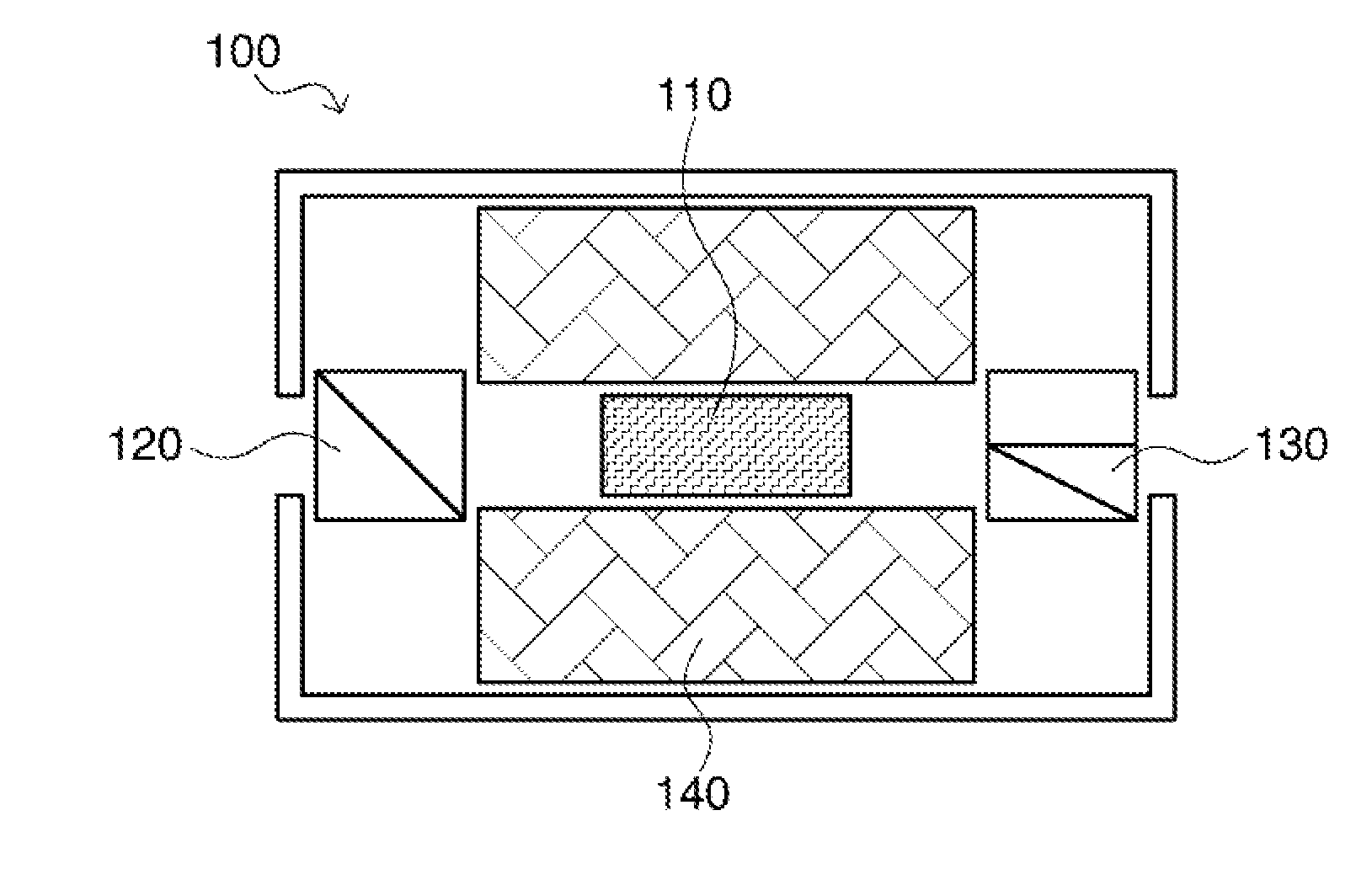
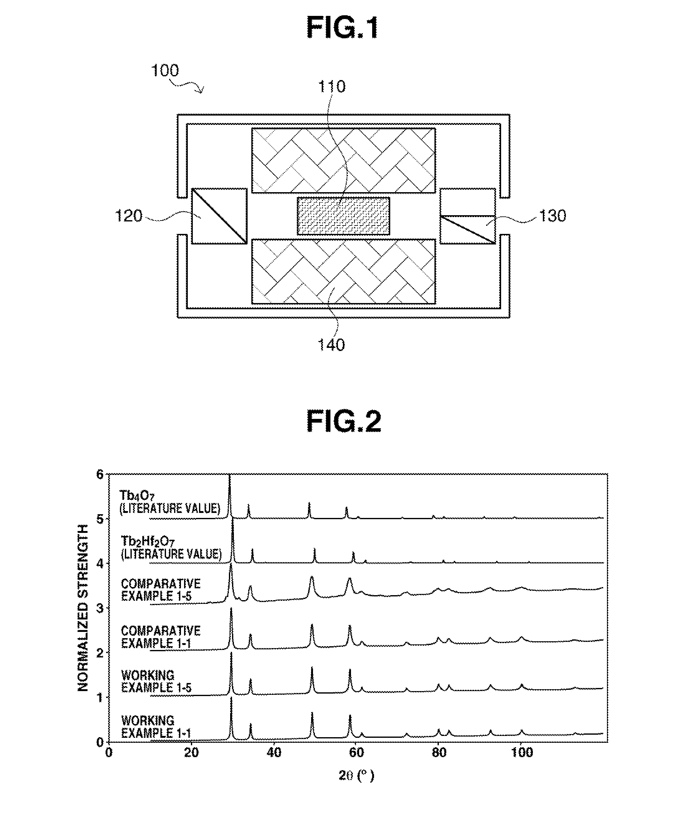
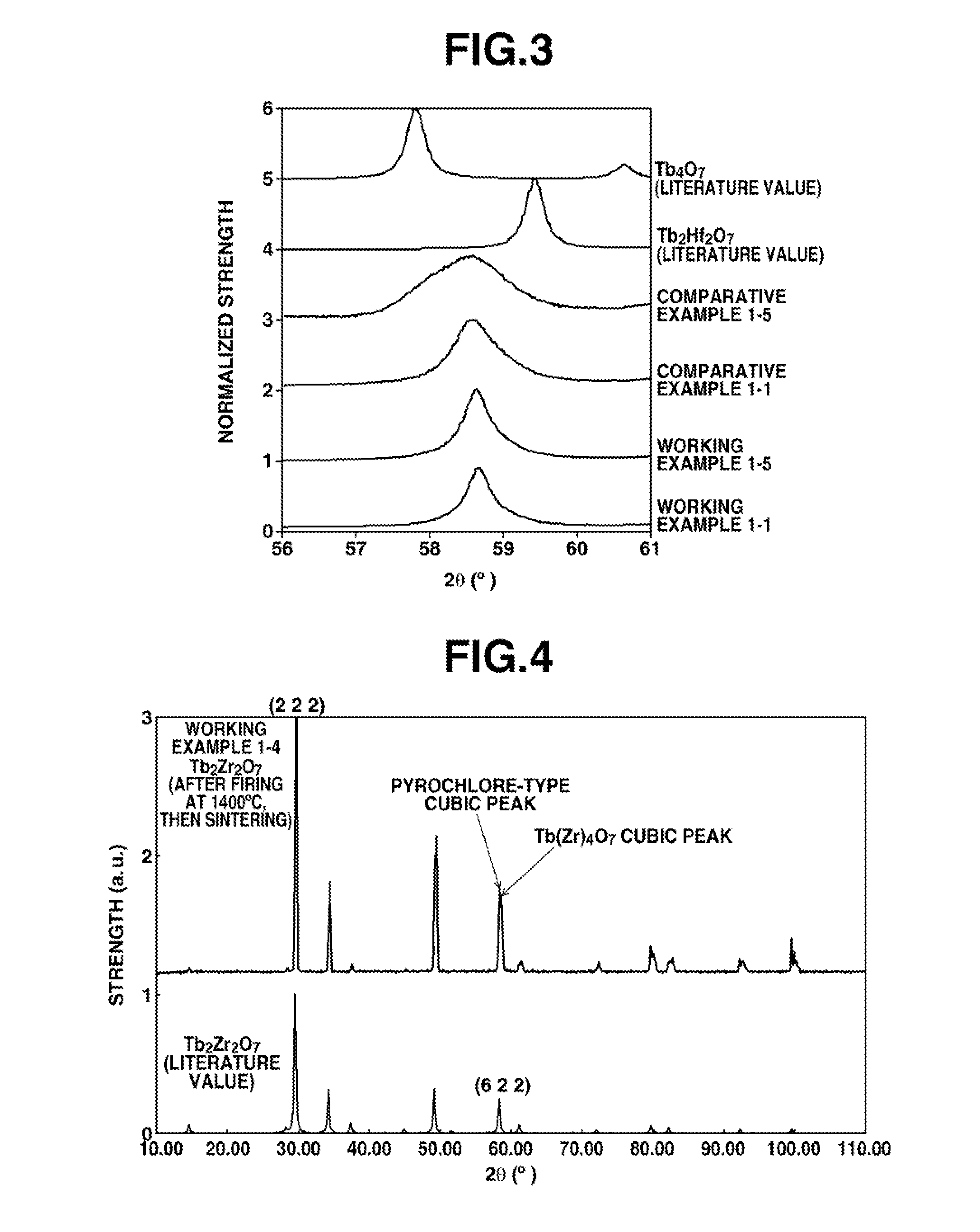
The invention provides transparent magneto-optical materials suitable for making magneto-optical devices such as optical isolators. These materials can be used in fiber laser systems without degrading the beam quality, and they have a Verdet constant that is larger than that of TGG crystals, which allows for miniaturization. The invention also provides a diagram showing an optical isolator utilizing the mentioned materials. The patent text describes the development of these materials through x-ray diffraction patterns analysis and working examples. Overall, the invention offers a solution for improving the performance and functionality of magneto-optical devices.

Problems solved by technology

However, the resonance state of the laser light source within a laser beam machine is destabilized by the entry of outside light, disturbing the oscillation state.
Disruption of the oscillation state is particularly severe when the light that has been generated is reflected by intermediate optics and returns to the light source.
With fiber lasers in recent years becoming increasingly high-powered, even when a laser is equipped with an optical isolator having only slight absorption, this leads to deterioration in beam quality on account of a thermal lens effect.
This makes optical isolators that use such yttrium iron garnet single crystals very difficult to employ in fiber laser systems where the trend is clearly toward higher power levels.
It is known, among those skilled in the art, that normal sintering alone usually yields an opaque sintered body, and so the materials described in Patent Document 6 presumably cannot be used in optical material applications.

Method used


Image

  • Magnetooptical material, manufacturing method therefor, and magnetooptical device
  • Magnetooptical material, manufacturing method therefor, and magnetooptical device
  • Magnetooptical material, manufacturing method therefor, and magnetooptical device

Examples


working example 1

Comparative Example 1

[0072]Examples are described here in which hafnium, tin, titanium or zirconium was selected as a single element to fill the B site positions (R in above formula (1)).

[0073]Terbium oxide powder produced by Shin-Etsu Chemical Co., Ltd., hafnium oxide powder produced by American Elements, stannic oxide powder and titanium oxide powder produced by Kojundo Chemical Laboratory Co., Ltd., and zirconia powder produced by Nissan Chemical Industries, Ltd. were procured. The purities were all at least 99.9 wt %.

[0074]Four pyrochlore-type oxide starting materials, these being Tb2Hf2O7, Tb2Sn2O7, Tb2Ti2O7 and Tb2Zr2O7, were produced using the above raw materials. That is, four mixed powders were prepared: a mixed powder obtained by weighing out terbium oxide and hafnium oxide so that the terbium and hafnium are in an equimolar ratio, a mixed powder obtained by weighing out terbium oxide and stannic oxide so that the terbium and tin are in an equimolar ratio, a mixed powder o...

working example 2

Comparative Example 2

[0110]Examples are described here in which at least one element selected from the group consisting of silicon, germanium, titanium, tantalum and tin was filled at the B site positions in above formula (1) to give compositions other than the compositions of Working Example 1.

[0111]Terbium oxide powder produced by Shin-Etsu Chemical Co., Ltd., silica powder, germanium dioxide powder, titanium oxide powder and stannic oxide powder produced by Kojundo Chemical Laboratory Co., Ltd., and tantalum pentoxide produced by Showa Chemical Industry Co., Ltd. were procured. The purities were all at least 99.9 wt %.

[0112]The following complex oxide starting materials were produced using these raw materials: a mixed powder obtained by weighing out terbium oxide, silica and zirconia in such a way that the molar ratio of terbium to silicon to zirconium is 2:1:1, a mixed powder obtained by weighing out terbium oxide, germanium dioxide and zirconia in such a way that the molar rati...

working example 3

[0121]Other examples are described in which hafnium or zirconium was selected for the B-site positions in formula (1).

[0122]Terbium oxide powder produced by Shin-Etsu Chemical Co., Ltd., hafnium oxide powder produced by American Elements, and zirconia powder produced by Nissan Chemical Industries, Ltd. were procured. The purities were all at least 99.9 wt %.

[0123]The two pyrochlore-type oxide starting materials Tb2Hf2O7 and Tb2Zr2O7 were produced using these raw materials. That is, the two following mixed powders were prepared: a mixed powder obtained by weighing out terbium oxide and hafnium oxide in such a way that the terbium and hafnium are in an equimolar ratio, and a mixed powder obtained by weighing out terbium oxide and zirconium oxide in such a way that the terbium and zirconium are in an equimolar ratio. Next, the mixed powders were dispersed and mixed in ethanol within a zirconia ball mill while being careful to prevent contamination between the different powders. The tre...


PUM

PropertyMeasurementUnit
diameteraaaaaaaaaa
diameteraaaaaaaaaa
diameteraaaaaaaaaa

Abstract

This invention provides a transparent magnetooptical material that is suitable for use in a magnetooptical device such as an optical isolator. Said magnetooptical material comprises either a transparent ceramic consisting primarily of a complex oxide that can be represented by formula (1) or a single crystal of such a complex oxide. Said magnetooptical material does not absorb fiber-laser light in the 0.9-1.1 μm wavelength range, does not cause heat lensing, and has a higher Verdet constant than TGG crystals, with a Verdet constant of at least 0.14 min / (Oe·cm) at a wavelength of 1,064 nm.Tb2R2O7  (1)(In formula (1), R represents one or more elements selected from among the group consisting of silicon, germanium, titanium, tantalum, tin, hafnium, and zirconium (but not silicon only, germanium only, or tantalum only).)

Description

TECHNICAL FIELD[0001]This invention relates to magneto-optical materials and magneto-optical devices. More particularly, the invention relates to magneto-optical materials that are made of a complex oxide-containing transparent ceramic or single crystal and are suitable for constructing magneto-optical devices such as optical isolators, and to a method of manufacturing such materials. The invention also relates to magneto-optical devices that use such magneto-optical materials.BACKGROUND ART[0002]In recent years, partly on account of the higher power levels that have become possible, there has been a remarkable growth in the use of laser beam machines which employ fiber lasers. However, the resonance state of the laser light source within a laser beam machine is destabilized by the entry of outside light, disturbing the oscillation state. Disruption of the oscillation state is particularly severe when the light that has been generated is reflected by intermediate optics and returns ...

Claims


Application Information

Patent Timeline
Patent Type & Authority Applications(United States)
IPC IPC(8): C30B29/22G02F1/09G02F1/00C30B1/12C30B29/32
CPCC30B29/22C30B1/12G02F1/093G02F1/0036C30B29/32G02F1/09C30B29/30C04B35/01C04B35/16C04B35/457C04B35/462C04B35/486C04B35/495C04B35/6261C04B35/6455C04B2235/3218C04B2235/3224C04B2235/3244C04B2235/3251C04B2235/3287C04B2235/3293C04B2235/3418C04B2235/5436C04B2235/6567C04B2235/661C04B2235/762C04B2235/77C04B2235/786C04B2235/80C04B2235/81C04B2235/9646C04B2235/9653
Inventor IKARI, MASANORI
Owner SHIN ETSU CHEM IND CO LTD
Learn More