Hydrothermal Cleanup Process

a technology of water and water, applied in the direction of liquid solution solvent extraction, separation process, water treatment, etc., can solve the problems of rapid desalting and rapid separation of water and organic phases with or without demulsification, and achieve the effects of reducing concentration, high product yield, and small footprin

Active Publication Date: 2016-07-28
APPLIED RES ASSOCS INC
View PDF15 Cites 26 Cited by
  • Summary
  • Abstract
  • Description
  • Claims
  • Application Information

AI Technical Summary

Benefits of technology

[0010]The present invention is directed to a process and system for the hydrothermal cleanup of renewable or non-renewable organic feedstocks, such as renewable plant oil, algal and microbial oils, waste vegetable oils, brown grease, tallow; oils from recycled petroleum products, plastics, and elastomers; and petroleum crude oil or crude oil fractions. This invention has numerous advantages over other cleanup processes such as chemical degumming, desalting processes, or other chemical, extraction, or thermal processes. Advantages include, but are not limited to: 1) equipment that exhibits a small footprint that can be co-located with a conventional refinery or implemented in the field; 2) the ability to recover valuable aqueous or organic products or byproducts; and 3) incorporation of integral high-energy atmospheric vapor-liquid separation or rectification of the product stream that eliminates the need for vacuum distillation to separate or concentrate products. The process and system of the invention results in a high product yield with significantly reduced concentrations of salts, metals, and minerals, such as silicas, oxides, carbonates, sulfates, and phosphates. The system is specifically desirable for use in processing unrefined plant oil, algal oils, waste vegetable oils, and oils from recycled plastic, elastomers, and petroleum crude oils or petroleum fractions such as atmospheric tower bottoms (ATB). At the elevated temperatures employed during hydrothermal cleanup, renewable oils and water become miscible, which results in rapid desalting and rapid separation of water and organic phases with or without demulsifying agents.

Problems solved by technology

At the elevated temperatures employed during hydrothermal cleanup, renewable oils and water become miscible, which results in rapid desalting and rapid separation of water and organic phases with or without demulsifying agents.

Method used


Image

  • Hydrothermal Cleanup Process
  • Hydrothermal Cleanup Process
  • Hydrothermal Cleanup Process

Examples


example 1

HCU Rapid Hydrolysis

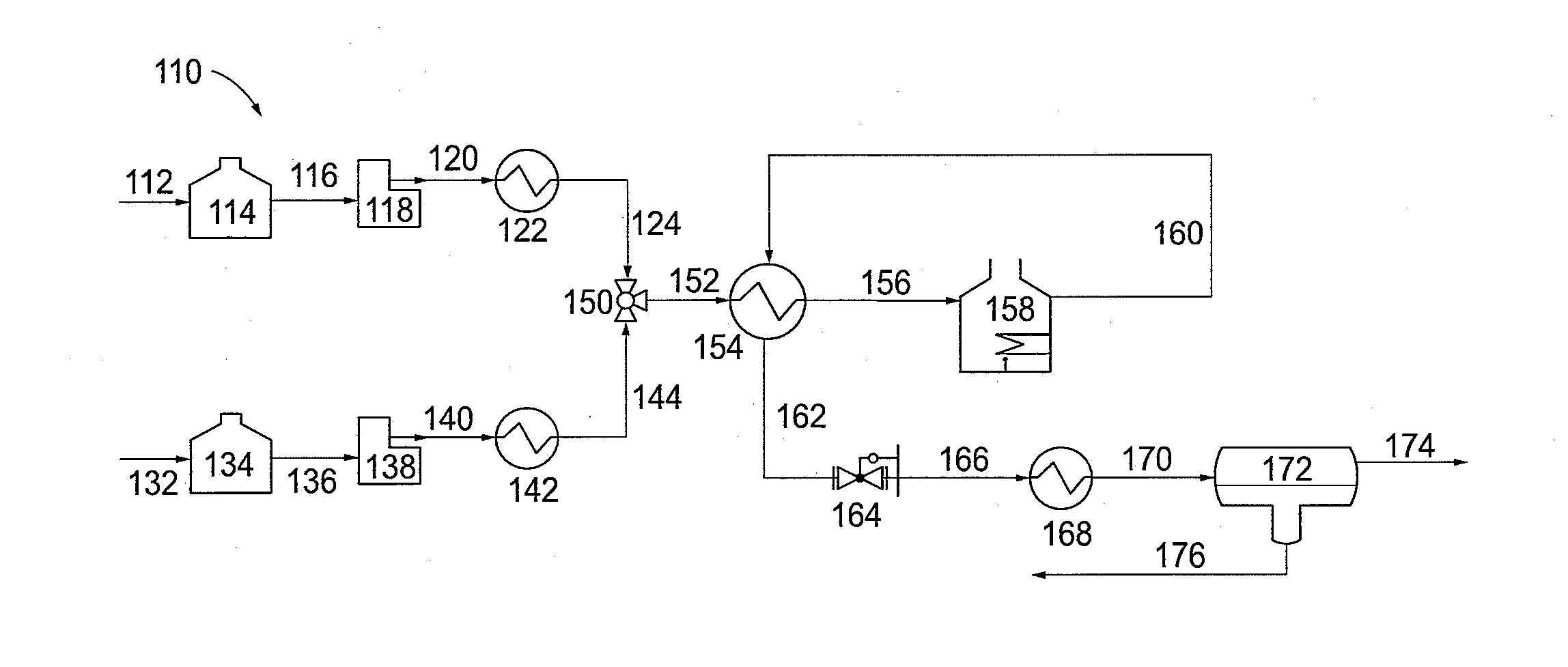
[0046]Unrefined soybean oil was used as the feedstock to a pilot scale HCU system configured as shown in FIG. 1 to conduct rapid hydrolysis at temperatures greater than 290° C. without glycerin decomposition. Actual operating conditions are provided in Table 1 with reactor temperature of 340° C. and reactor pressure controlled at 2,500 psig to maintain the reaction mixture in the liquid phase. At these conditions, the triglyceride feedstock, water, and products of hydrolysis (glycerin and free fatty acids) are miscible. The very short residence time in liquid phase, and relatively low concentration of glycerin, resulted in near complete hydrolysis and inhibited glycerin decomposition. Upon cooling via the feed-effluent heat exchanger and product cooler, an organic phase containing FFAs and an aqueous phase containing glycerin and water were separated in an oil-water separator.

TABLE 1HCU Operating Conditions for Rapid HydrolysisParameterValueSoybean oil flow rate,...

example 2

Hydrothermal Cleanup of Yellow and Brown Grease

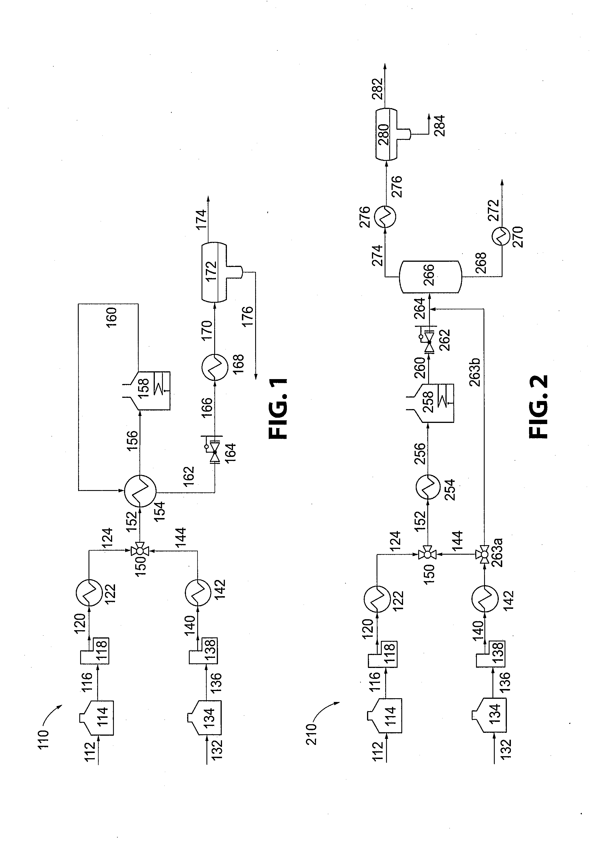
[0049]A pilot HCU system was configured as shown in FIG. 2. The vapor-liquid separation system was a flash drum modified with internal packing to aid in demisting the vapor product. No external reflux was provided for rectification of the overhead product. The feedstock consisted of a 60:40 blend of yellow grease (YG) and brown grease (BG). The brown grease acquired for this example had been dewatered and filtered. The feedstocks were desalted using a simple water wash and blended before processing by HCU. A summary of HCU operating conditions for this example is provided in Table 3.

TABLE 3Summary of HCU Operating Conditions for Waste Oil CleanupParameterValue60:40 YG:BG flow rate, mL / min135Specific gravity of 60:40 YG:BG blend, g / cc0.948Water flow rate, mL / min135Total flow rate, mL / min270Water fraction of total feed, vol %50Reactor temperature, ° C.450Reactor pressure, psig500Superficial residence time, sec120Actual hydraulic residence...

example 3

Phospholipid Cleanup

[0052]A feedstock that is high in phospholipid content and other inorganic contaminants was processed. This feedstock was comprised of partially refined microbial oils and plant oils that contained a broad mixture of lipid types including triglycerides, phospholipids, alcohols, and long chain waxy esters. At HCU operating conditions, phospholipid molecules and triglycerides are rapidly hydrolyzed as demonstrated in Example 1. Phosphorus from the phospholipids is mostly liberated as phosphate ion (PO43−).

[0053]In this example rapid hydrolysis was performed in the HCU system configured as shown in FIG. 1. The HCU reactor was controlled at 2,500 psig and 340° C. to maintain the reaction mixture in the liquid phase. Table 5 provides a summary of the operating conditions. At these conditions, the feedstock, water, and products of hydrolysis (glycerin, FFAs, and inorganics) are miscible. Upon cooling via a feed-effluent heat exchanger and cooling heat exchanger, an org...


PUM


Abstract

A high-rate hydrothermal cleanup (HCU) process and system is disclosed for the rapid hydrolysis of renewable oils and reduction of inorganic and organic contaminants, such as salts, minerals, metals, asphaltenes, polymers, and coke precursors in both renewable oils and petroleum fractions. The process and system is characterized by a very short residence time, high-temperature, high-pressure, turbulent flow, hydrothermal operation. The HCU and integrated vapor-liquid separation system and process results in high yields of oil product that contains significantly reduced concentrations of inorganic and organic contaminants. The process may be operated to produce a concentrated clean glycerin byproduct and short-chain and long-chain free fatty acid product streams. The integrated vapor-liquid separation system and process performs at near atmospheric pressure by taking advantage of the water employed in the cleanup process and the energy imparted by the HCU reactor and eliminates the need for vacuum distillation.

Description

CROSS REFERENCE TO RELATED APPLICATIONS[0001]This application claims benefit of priority from U.S. Provisional Patent Application No. 62 / 108,770, filed Jan. 28, 2015, which is incorporated herein by reference in its entirety.FIELD OF THE INVENTION[0002]The present invention is directed to a hydrothermal cleanup (HCU) process and system for the rapid hydrolysis of renewable oils and reduction of inorganic and organic contaminants, such as salts, minerals, metals, asphaltenes, and coke precursors in both renewable oils and petroleum fractions. The process and system is characterized by a very short residence time, high-temperature, high-pressure, turbulent flow, hydrothermal operation.BACKGROUND OF THE INVENTION[0003]The ever-increasing demand for renewable fuels and chemicals has forced refineries to look to alternative hydrocarbon sources and ways to upgrade and convert these sources or feedstocks into viable products. In particular, refineries need processes to upgrade renewable an...

Claims


Application Information

Patent Timeline
Patent Type & Authority Applications(United States)
IPC IPC(8): B01D3/14B01D11/04
CPCB01D11/04B01D3/143B01D3/009C10G31/06C10G31/08Y02P30/20C07C7/08B01D17/0214C07C7/04
Inventor COPPOLA, EDWARD N.RED, JR., CHARLESNANA, SANJAY
Owner APPLIED RES ASSOCS INC
Why Eureka
Try Eureka