Separator for electrochemical device

a technology of electrochemical devices and separators, which is applied in the direction of electrochemical generators, cell components, cell component details, etc., can solve the problems of very severe change in fibril morphology on the surface, negative influence on cycle characteristics, etc., and achieves the reduction of porosity, final thickness, and mechanical strength.

Active Publication Date: 2016-07-28
LG CHEM LTD
View PDF5 Cites 16 Cited by
  • Summary
  • Abstract
  • Description
  • Claims
  • Application Information

AI Technical Summary

Benefits of technology

[0036]The separator according to an exemplary embodiment of the present disclosure has an increase in the mechanical strength and a reduction in thickness, because a heat-resistant organic/inorganic both-side coating process is performed after film formation of a fabric with an optimal stretching magnification before heat setting, and heat setting is performed at a higher temperature than traditional heat setting, to manufacture a porous polymer film, in which a binding density of fibrils increases by the high quantity of heat.
[0037]That ...

Problems solved by technology

However, an organic/inorganic heat-resistant coating layer serves as a resistive layer which blocks a flow of lithium ions and has a negative influence on cycle characteristics.
During heat setting, a wet p...

Method used


Image

  • Separator for electrochemical device
  • Separator for electrochemical device
  • Separator for electrochemical device

Examples


example 1-1

Manufacture of Separator

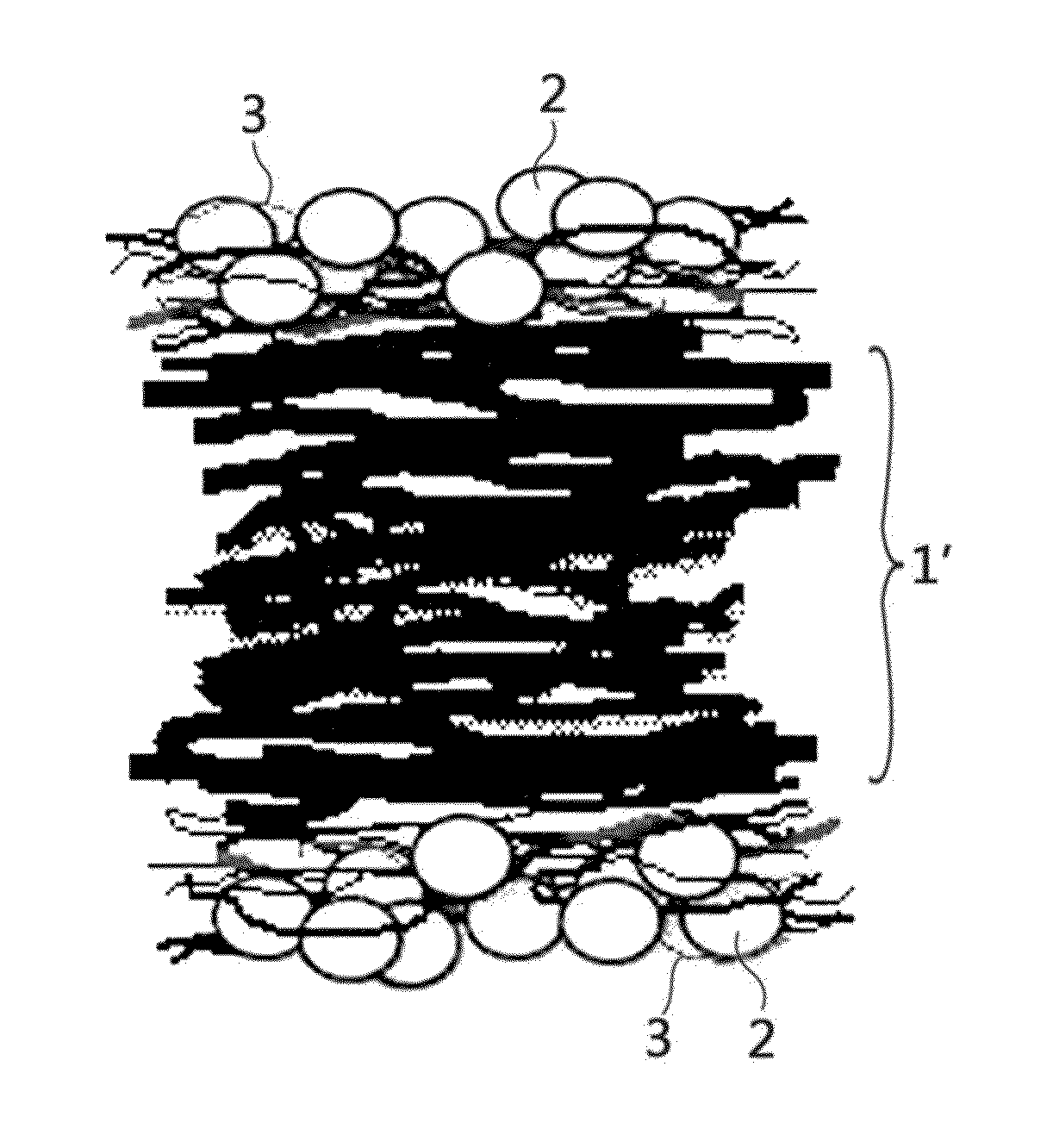
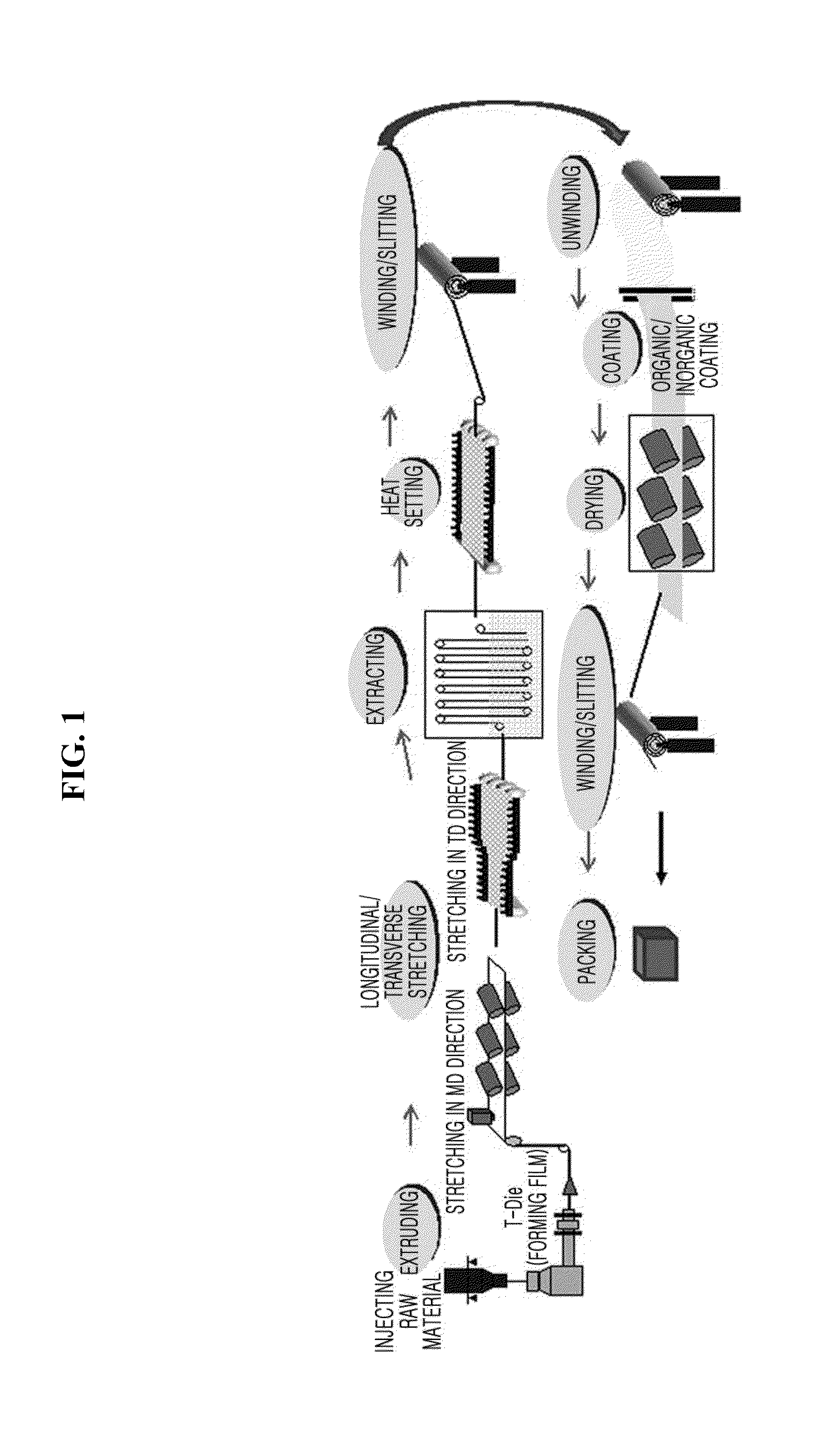
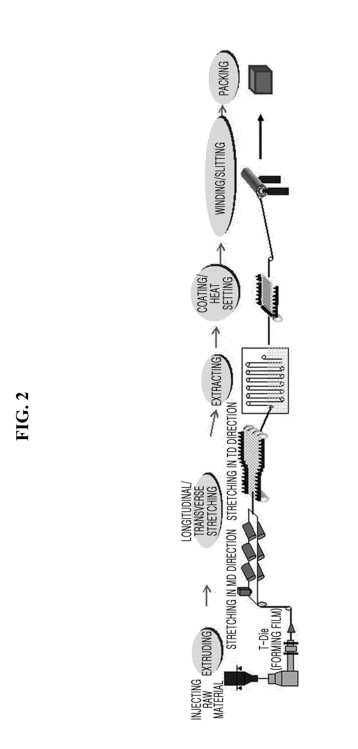
[0143]High density polyethylene with a weight average molecular weight of 500,000 as polyolefin and liquid paraffin with a kinematic viscosity of 68.00 cSt as a diluent were extruded using a weight ratio of 35:65 at the temperature of 210° C. Stretching was performed at a stretching temperature of 115° C., and a stretch ratio of seven times each in a longitudinal direction and a transverse direction. Subsequently, the diluent, i.e., the liquid paraffin was extracted using methylene chloride as an extraction solvent under the condition of 2 m / min to obtain a porous polyolefin film with an average pore size of 0.04 μm.

[0144]Subsequently, Al2O3 particles with an average grain diameter of 0.5 μm / cyanoethylpolyvinylalcohol (Cyano resin CR-V, Shin-Etsu Chemical, Ltd.) / PVDF-HFP5 (LBG2, Arkema, Inc.) / acetone was mixed at a weight ratio of 18.0 / 0.3 / 1.7 / 80 to prepare a slurry for forming a porous layer.

[0145]The slurry was coated in a thickness of 3.5 μm on one surface...

example 1-2

Manufacture of Separator

[0146]A separator was manufactured by the same method as Example 1-1, except that the slurry was coated in a thickness of 4.0 pin on both surfaces and a thickness of the separator is 19.0 μm. The porous coating layer of the separator has an average pore size of 0.4 μm and an average porosity of 55%.

example 1-3

Manufacture of Cylindrical (18650) Secondary Battery

[0147]Ethylene carbonate, propylene carbonate, and methyl ethyl carbonate compounds were used at a composition ratio of 20 / 10 / 70 based on a volumetric ratio. Subsequently, LiPF6 as a lithium salt was added to a concentration of 1.0M to obtain a non-electrolyte solution.

[0148]With the use of a ternary system cathode material (LiNi1 / 3CO1 / 3Mn1 / 3O2) as a cathode active material, a cathode mixture including 1.3 wt % of Super-P (registered trademark) as a conductive material, 1.8 wt % of PVDF(KF1100 binder), and 0.4 wt % of Li2CO3(lithium carbonate) as an additive was added to a solvent NMP(N-methyl-2-pyrrolidone) to prepare a cathode slurry with solids of 75%, which was then coated on an aluminum current collector to manufacture a cathode.

[0149]With the use of graphite as an anode active material, 0.7 wt % of Super-P (registered trademark) as a conductive material, approximately 0.9 wt % of a SBR binder, and approximately 0.9 wt % of a ...


PUM

PropertyMeasurementUnit
Temperatureaaaaaaaaaa
Fractionaaaaaaaaaa
Thicknessaaaaaaaaaa

Abstract

Disclosed is a separator for an electrochemical device including a porous polymer film, and a porous coating layer including at least one type of particles of inorganic particles and organic particles and binder polymer, the porous coating layer formed on one surface or both surfaces of the porous polymer film, wherein the porous polymer film has a structure in which multiple fibrils arranged parallel to the surface of the film are stacked in layers, and the fibrils are bound to each other to form a lamellar structure with a size from 130 to 200 nm and tortuosity of the porous polymer film is from 1.60 to 1.90, and an electrochemical device comprising the same.

Description

TECHNICAL FIELD[0001]The present disclosure relates to a separator for an electrochemical device, and more particularly, to a separator for an electrochemical device that exhibits improved hipot characteristics and enhanced mechanical and thermal performance, has a low tortuosity value, and contributes to cycle characteristic improvement of an electrochemical device.[0002]The present application claims priority to Korean Patent Application No. 10-2013-0157285 filed in the Republic of Korea on Dec. 17, 2013, the disclosure of which is incorporated herein by reference.[0003]Also, the present application claims priority to Korean Patent Application No. 10-2013-0165969 filed in the Republic of Korea on Dec. 27, 2013, the disclosure of which is incorporated herein by reference.[0004]Also, the present application claims priority to Korean Patent Application No. 10-2014-0182526 filed in the Republic of Korea on Dec. 17, 2014, the disclosure of which is incorporated herein by reference.BACK...

Claims


Application Information

Patent Timeline
IPC IPC(8): H01M2/16H01M2/18H01M10/0525H01M50/406H01M50/414H01M50/431H01M50/443H01M50/449H01M50/489H01M50/491H01M50/494
CPCH01M2/166H01M2/1666H01M2/18H01M10/0525H01M2/162H01M10/052C09D123/06Y02E60/10H01M50/44H01M50/449H01M50/446H01M50/491H01M50/414H01M50/443H01M50/431H01M50/489H01M50/406H01M50/494H01M2300/0085H01M50/451H01M50/454H01M50/417H01M50/463B32B27/14B32B2457/00
Inventor RYU, BI-OHYOON, KYUNG-HWANSONG, HEON-SIK
Owner LG CHEM LTD
Why Eureka
Try Eureka