Modified vacuum actuated valve assembly and sealing mechanism for improved flow stability for fluids sub-atmospherically dispensed from storage and delivery systems

Active Publication Date: 2016-09-08
PRAXAIR TECH INC
View PDF15 Cites 31 Cited by
  • Summary
  • Abstract
  • Description
  • Claims
  • Application Information

AI Technical Summary

Benefits of technology

The invention introduces enhancements to a vacuum actuated valve assembly and sealing mechanism to improve the flow stability of fluids dispensed from storage and delivery systems.

Problems solved by technology

Due to their extreme toxicity and high vapor pressure, their use, transportation and storage raise significant safety concerns for the semiconductor industry.
As such, a fail-safe vacuum-actuated valve design is required.
There are certain limitations associated with the SDS technology, and they include the following: 1) the adsorbent material has a finite loading capacity thereby limiting the amount of product available in a given size cylinder; 2) the desorption process can be initiated by exposing the cylinder package to heat, thereby causing the cylinders to reach and deliver gases at atmospheric and super-atmospheric pressures when the cylinder is exposed to temperatures greater than 70° F., which are common in many cylinder warehouse locations and within the ion implant tool; 3) the purity of the gas delivered from the cylinder can be compromised due to adsorption / desorption of the other materials / gases on the adsorbent material; 4) cylinder utilization is influenced by the depth of vacuum applied to the package, such that cylinders can often be returned with appreciable unused product remaining in the package; and 5) adsorbent attrition can lead to particulate contamination in the gas delivery system.
Despite the related storage and delivery systems, sub-atmospheric flow instability continues to be a significant problem.
Ion implant tools tend to be sensitive to such delivery pressure spikes and oscillations, as the flow instability creates flow spikes which can automatically shut down an ion implant tool at a semiconductor fabrication plant, thereby resulting in increased down time for the semiconductor manufacturer.
Additionally, there are instances when the pin-poppet valve design problematically does not dispense gas at desired downstream vacuum conditions.

Method used


Image

  • Modified vacuum actuated valve assembly and sealing mechanism for improved flow stability for fluids sub-atmospherically dispensed from storage and delivery systems
  • Modified vacuum actuated valve assembly and sealing mechanism for improved flow stability for fluids sub-atmospherically dispensed from storage and delivery systems
  • Modified vacuum actuated valve assembly and sealing mechanism for improved flow stability for fluids sub-atmospherically dispensed from storage and delivery systems

Examples


example 1

Modified Valve Assembly; 15% Xe—H2 at 1200 psig; FIG. 7 Test

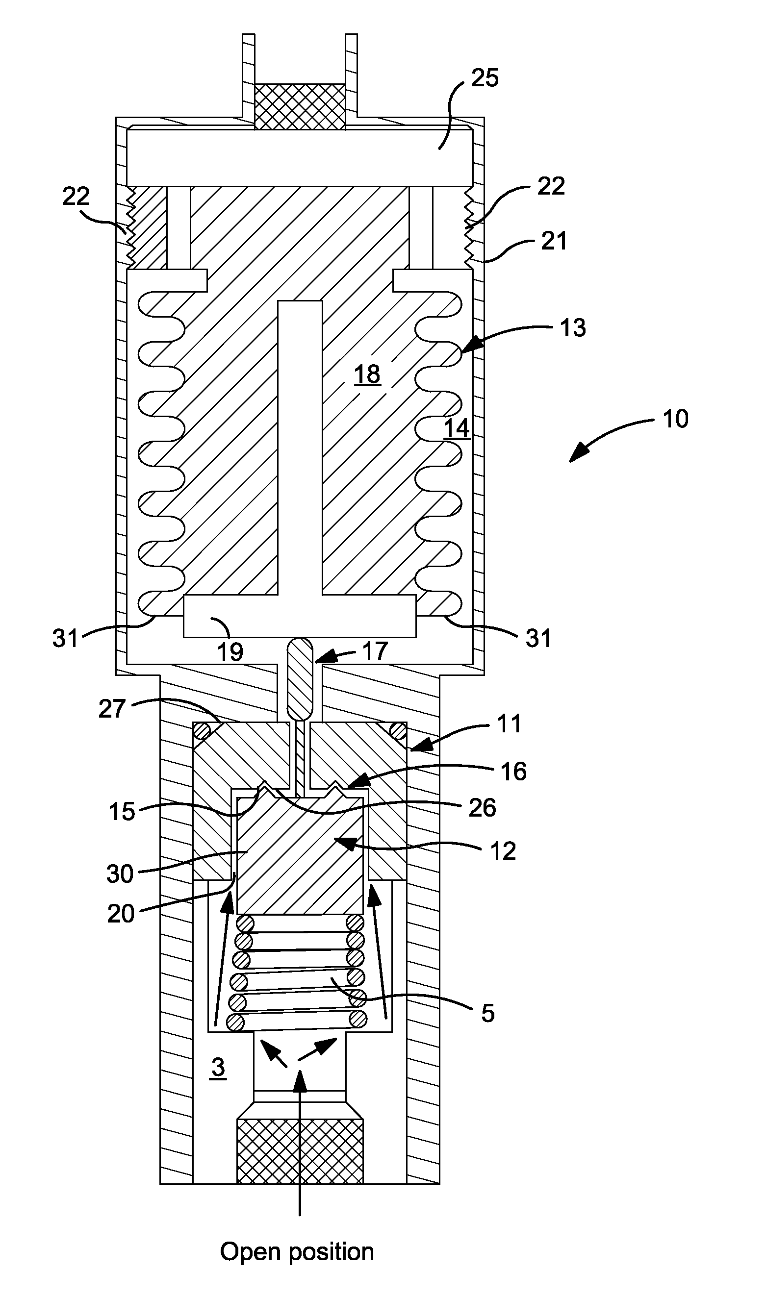
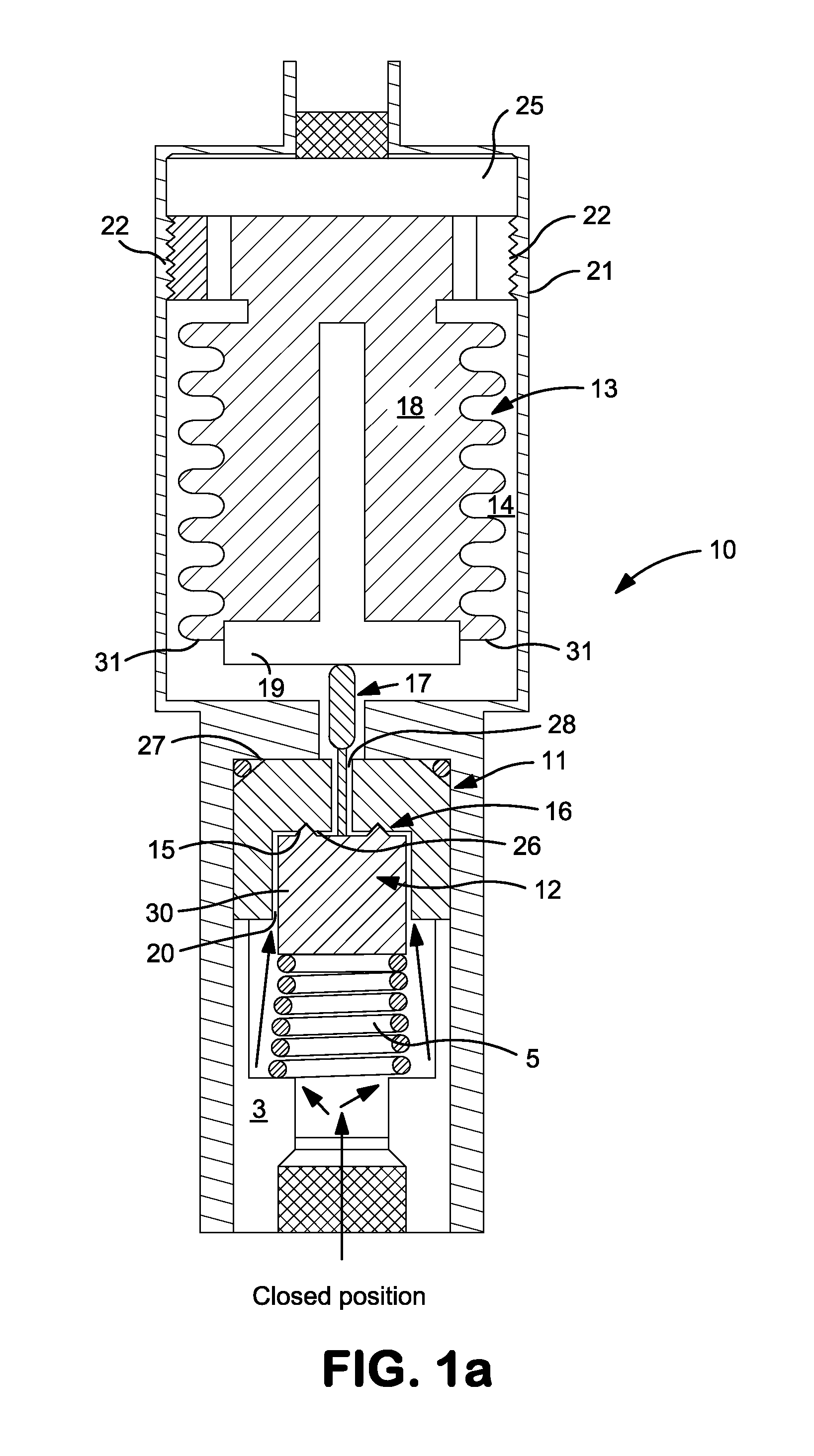
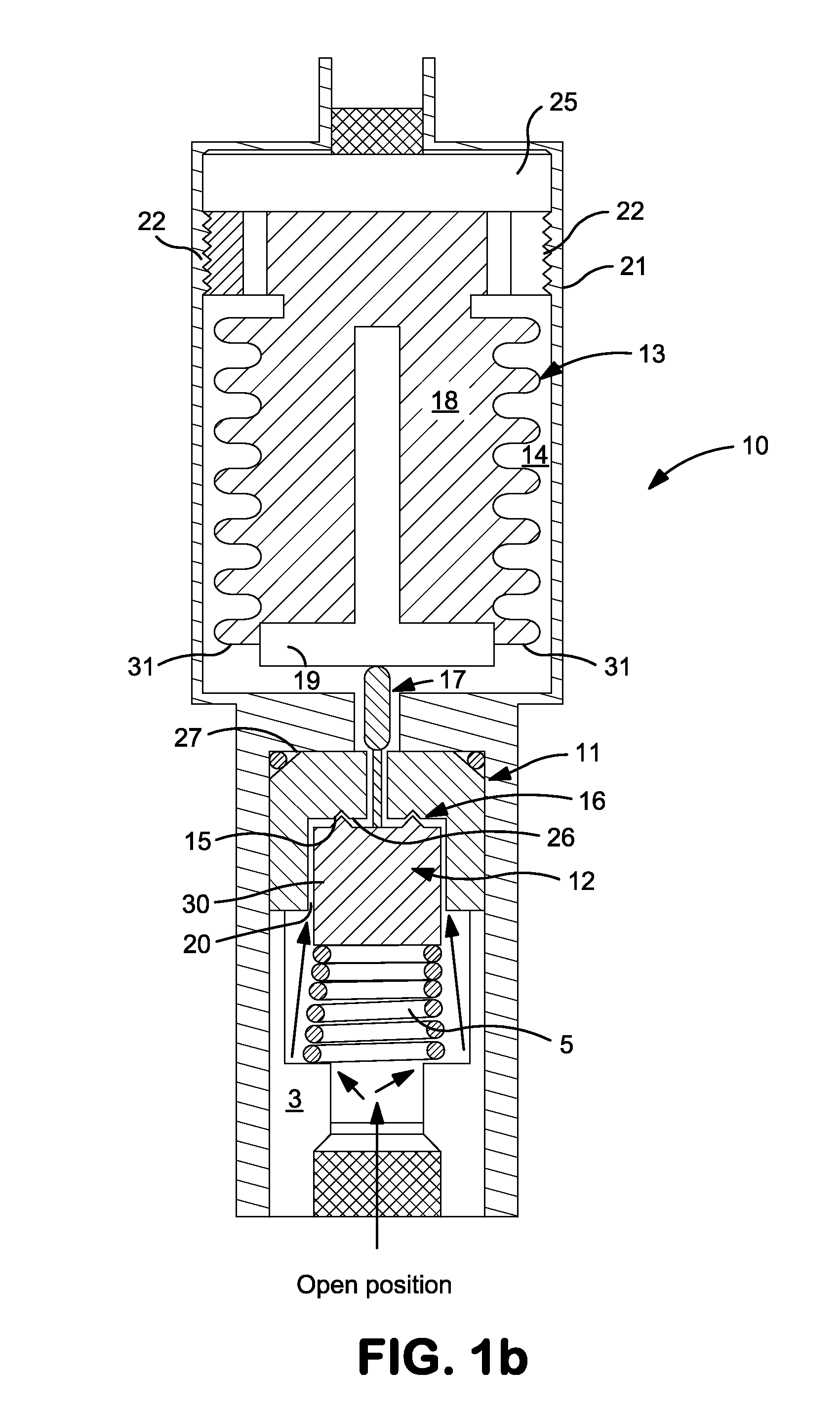
[0088]The modified vacuum actuated valve assembly of the present invention, as shown in FIGS. 1a-1c, was inserted into a gas sub-atmospheric delivery and high pressure storage cylinder. A flow test was conducted to evaluate the valve opening behavior of the modified valve assembly. A gas mixture of 15% Xe and the balance hydrogen (Xe—H2) was filled into the cylinder so that the inlet pressure onto the valve assembly was 1200 psig. The cylinder was connected to a flow manifold that was configured identically as described in Comparative Examples 1 and 2. The flow test was performed under the same conditions as described in the Comparative Examples 1 and 2.

[0089]At approximately 50 seconds into the test, the modified valve assembly was actuated into the open position to dispense Xe—H2. FIG. 7 shows no delivery pressure spikes or oscillations occurred upon opening of the valve. As a result, the flow rate as measured by the mass...

example 2

Modified Design; BF3 at 1200 psig; FIG. 8 Test

[0091]The modified vacuum actuated valve assembly of the present invention, as shown in FIG. 1, was inserted into a gas sub-atmospheric delivery and high pressure storage cylinder. A flow test was conducted to evaluate the valve opening behavior of the modified valve assembly utilizing the same protocol as in Comparative Example 2. BF3 gas was filled into the cylinder so that the inlet pressure onto the valve assembly was 1200 psig. The cylinder was connected to a flow manifold that was configured as in Comparative Examples 1 and 2 and Example 1. The flow test was performed under the same conditions as Comparative Examples 1 and 2 and Example 1.

[0092]At approximately 50 seconds into the test, the modified valve assembly opened. FIG. 8 shows no delivery pressure spikes occurred upon opening of the valve. As a result, the flow rate as measured by the mass flow controller remained steady at its target value of 0.5 sccm. The modified valve e...

example 3

Modified Valve Assembly; 40,000 Cycles+13 Day BF3 Hold at 1280 psig; FIGS. 9A and 9B Test

[0095]The modified vacuum actuated valve assembly of the present invention was inserted into a gas sub-atmospheric delivery and high pressure storage cylinder, as shown in FIG. 1. The flow stability of the valve assembly was evaluated at a range of flow rates after subjecting the valve assembly to the same conditions as in Comparative Example 3, namely a series of various tests which totaled 40,000 cycles followed by a 13 day hold of BF3 at 1250 psig and 104° F. A single open and closing of the valve assembly designated a single cycle. Each cycle was performed using BF3 gas. The valve was opened and closed for 5000 cycles followed by conducting a run-down test that consisted of flowing BF3 at 4 sccm from the cylinder at a pressure of 1250 psi until the cylinder approached an empty condition. This protocol was repeated until a total of 40,000 cycles were completed. Next, flow tests were performed...


PUM


Abstract

A modified vacuum actuated valve assembly and sealing mechanism is provided for improved sub-atmospheric flow stability characterized by the absence of delivery pressure spikes and flow excursions. The valve assembly includes a non-stationary thermoplastic seat and a stabber. The stabber is characterized by a top portion having a circular periphery designed to mechanically engage and disengage with an inner sealing surface of the thermoplastic seat. The sealing surface is coined to eliminate surface irregularities contained therein, thereby producing a relatively smooth coined mating inner sealing surface for the circular top portion of the stabber. The valve assembly also includes a modified bellows capable of fine tuning the delivery pressure of the valve assembly.

Description

FIELD OF INVENTION[0001]The present invention relates to a storage and delivery system having a modified and improved vacuum-actuated valve assembly to prevent the discharge of fluid from a vessel, such as a pressurized cylinder or tank and dispense the fluid upon application of a predetermined vacuum condition existing on the downstream side of the valve assembly.BACKGROUND[0002]Industrial processing and manufacturing applications require the use of highly toxic fluids. The manufacture of semiconductor materials represents one such application wherein the safe storage and handling of highly toxic hydride or halide gases and mixtures thereof becomes necessary. Examples of such gases include silane, germane, ammonia, phosphine, arsine, boron trifluoride, stibine, hydrogen sulfide, hydrogen selenide, hydrogen telluride, phosphorous trifluoride, arsenic pentafluoride and other halide or hydride compounds and gas mixtures thereof. As a result of toxicity and safety considerations, these...

Claims


Application Information

Patent Timeline
IPC IPC(8): F16K1/36
CPCF16K1/36F17C13/04G05D16/0622F17C2201/0114F17C2201/058F17C2203/0617F17C2205/0329F17C2205/0338F17C2205/0385F17C2205/0391F17C2205/0394F17C2221/037F17C2223/0123F17C2223/0153F17C2223/033F17C2223/036F17C2225/0123F17C2225/038F17C2270/0518F16K1/303Y02E60/32
Inventor HEIDERMAN, DOUGLAS C.SINHA, ASHWINI K.CRVELIN, PAULVASSALLO, ANDREW
Owner PRAXAIR TECH INC
Why Eureka
Try Eureka