Industrial process using a forced-exhaust metal furnace and mechanisms developed for simultaneously producing coal, fuel gas, pyroligneous extract and tar

a metal furnace and industrial process technology, applied in the direction of mechanical equipment, mechanical conveying coke ovens, machines/engines, etc., can solve the problems of high production cycle, high energy waste, and high production cost, and achieve the effect of reducing the number of furnace operators, and reducing the number of furnaces

Inactive Publication Date: 2019-04-04
BOCAIUVA MECANICA
View PDF2 Cites 0 Cited by
  • Summary
  • Abstract
  • Description
  • Claims
  • Application Information

AI Technical Summary

Benefits of technology

[0031]For this, the Container Furnace has a bipartite discharge valve, located in the lower region of the furnace, whose function is to release to base the charcoal produced without waiting for the cooling step. With the inclusion of the lower discharge valve the availability of the Container furnace for the productive process is increased considerably, reducing the number of investment in furnaces. Although the vent valve is the key element for this inventive jump, the proposed solution consists of a series of points, which together enable the unloading of coal, still red-hot, safely and quickly. This design allows the furnace to be designed and manufactured with adequate thermal insulation, i.e., light and efficient. The results of energy balance showed that in this way, the thermal losses of this furnace is less than 5% of all the energy contained in the firewood, this fuel with a moisture content of below 30%. The second advantage derived from this invention is the design and fabrication of a container own for receiving coal still in carbon fixation step, i.e., above 400° C. It is a metallic cylinder, but with low weight, below 4 tons, with no insulation and equipped with a unique system of water sprinklers on the coal during the unloading. This controlled water spray system over the falling down coal does not interfere with the mechanical properties thereof, since the amount of water does not exceed the volume required only for enthalpic energy removal or vaporization thereof. And especially, the water spray reduces by more than 70% the time needed for coal cooling in the proper carbonization furnace without loss of their mechanical properties and also without unintentional and uncontrolled maintenance of carbon fixation process that occurs in other prior art furnaces.
[0032]The furnace charging process was also optimized. Instead of loading the furnace from the bottom, as described in the prior art, the present invention, object of this report proposes a loading system from the upper part of the furnace, eliminating the necessity to rotate, tilt or tip over the furnace for loading. This improvement over prior art considerably reduces the charging time of the furnaces, resulting in productivity gain by increasing the availability of the furnace for the carbonization process. Charging from the top also allows a better homogenization of the load and greater operational regularity.

Problems solved by technology

In Brazil, most of the charcoal production, around 70% comes from the traditional charcoal kilns of brick kilns, said “rabo-quente furnace.” These furnaces have a low percentage yield by weight in the conversion of biomass into charcoal and have high long production cycles.
In the traditional process for producing coal in brick kilns type “Rabo-quente”, wood and coal are respectively loaded and unloaded manually, subjecting the furnace operator to severe and harsh working conditions.
In addition, generated gases in the carbonization process are released into the atmosphere without any control and / or use, resulting in a significant energy waste.
The released gases by these furnaces still harm the operators working environment, as the smoke released when in contact with eyes and mucous membranes cause irritation and may also contain toxic substances.
This system, although it has been proposed to solve the problems mentioned above, such as shorter carbonization time and improve process control and improve working conditions for workers, not completely cover all energy, environmental and operational issues.
Furthermore, the system is equipped with only one control valve, which for small volumes can be acceptable, but for industrial furnaces of large volume, such as on the proposal of this invention are not effective, being necessary the process control in several points of the furnace.
Although the PI 0506224-1 document deals with the Container furnace functionality as a gasifier, is not offered a definitive solution to the production of large scale charcoal, since the charcoal yield in a carbonization furnace which operates as a gasifier is low compared to the traditional process.
However, it still does not present complete solutions for environmental mechanization, automation and optimization, energetics and operational, which will be demonstrated in this application.
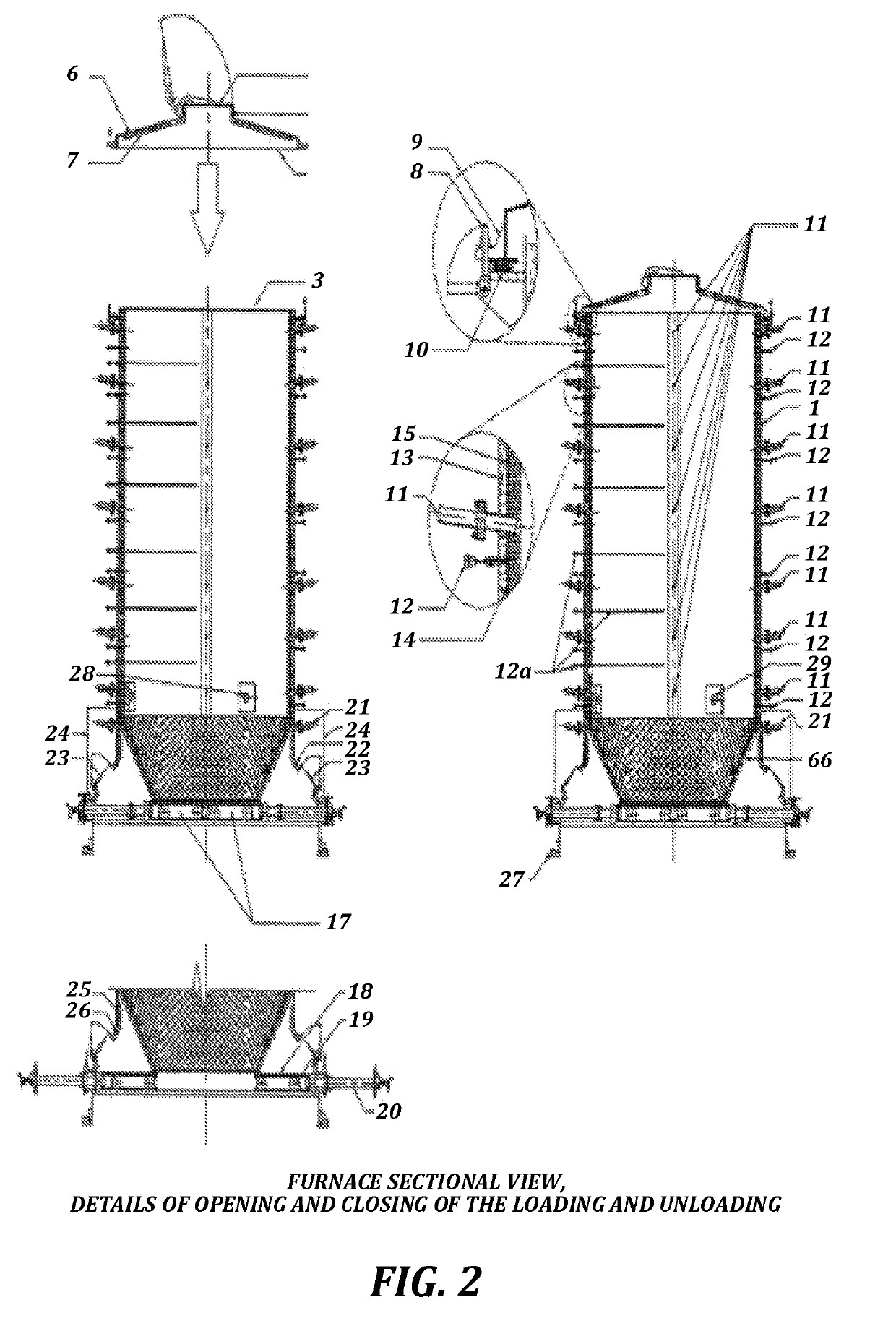
Furthermore, the document does not disclose a proposal to solve the rapid or instantaneous unloading the furnace.
However, in the course of development of this research, technically, the addition of two or more exhaust points leads to the need for greater control over the process due to different carbonization fronts formed.
In addition, ignition points at different positions in height and circumference of the furnace lead to unsafe operation because gases generated by one of the carbonization fronts may come into contact with the produced flame / coal by another front.
Depending on the temperature and hydrogen content, water vapor and oxygen in these areas, there is a risk of explosion.
In addition, this system does not propose a global solution, that make it viable, technically, economically, environmentally and energetically the operation of an industrial plant for production of charcoal.
In summary, the presented solution tries to solve the problems inherent to industrial process of charcoal production, but it fails when again it back using the furnace, dimensioned object and designed to withstand the high temperatures, to promote cooling.
Again this solution still does not show a global innovation as the optimization and energetic efficiency, environmentally and operationally of the process for nullifying the exclusive use of the furnace for the carbonization process, for not presenting detailed solutions of mechanization, automation and control.
Another flaw presented in the process concerns the proposals for loading and unloading the furnace.
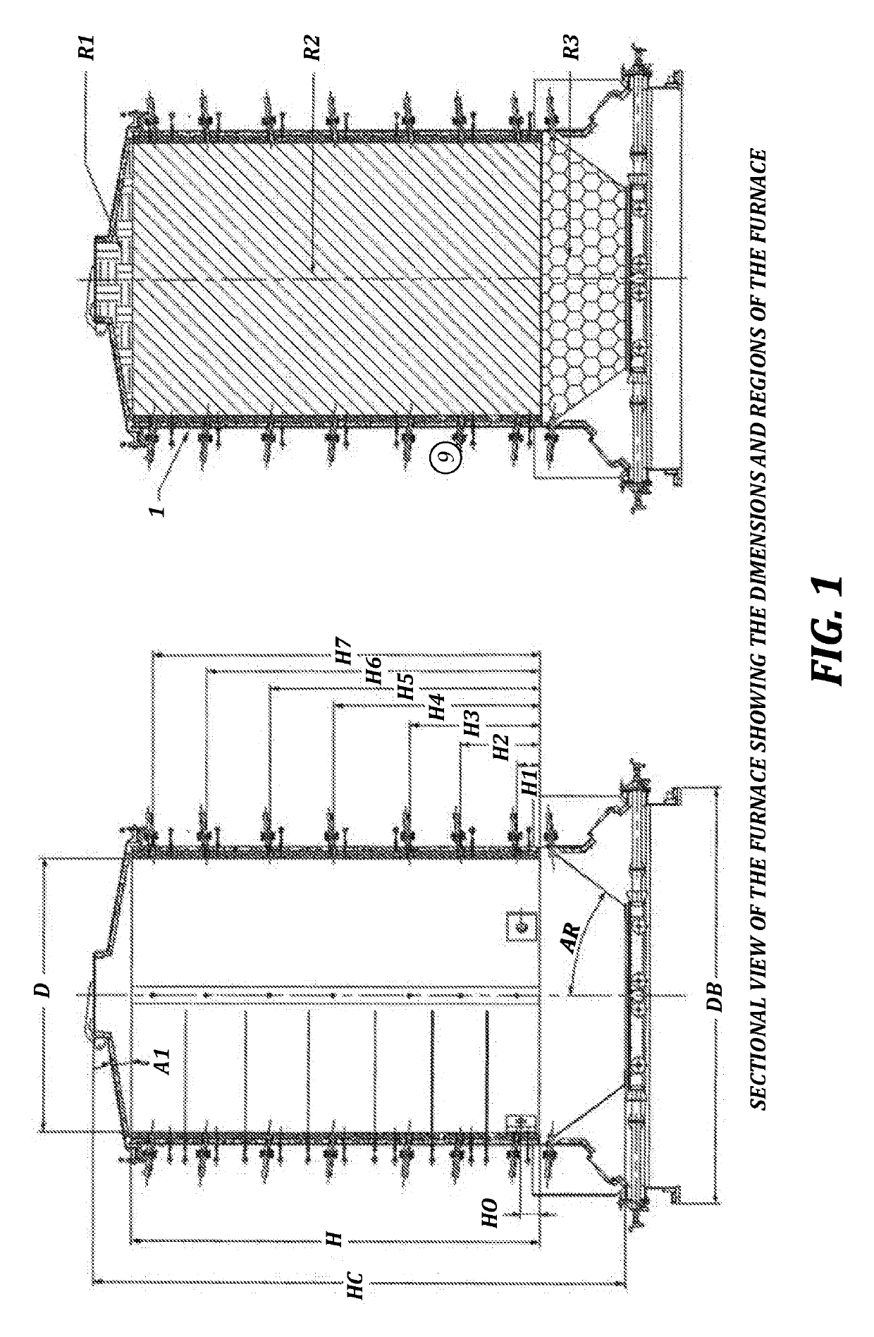
“Topple” the furnace, in other words, remove it from the vertical position and rotate it to landscape, results in a complicated process, especially when working with large capacity furnaces (up to 30 m3 of usable volume).
The needed equipment to carry out these operations are costly, decharacterizing the industrial application of this type of loading / unloading for an industrial furnace.
Another aspect to be considered refers to the sizing of the furnace, which should have structural reinforcements to meet the proposed charging, resulting in an increase in design cost.
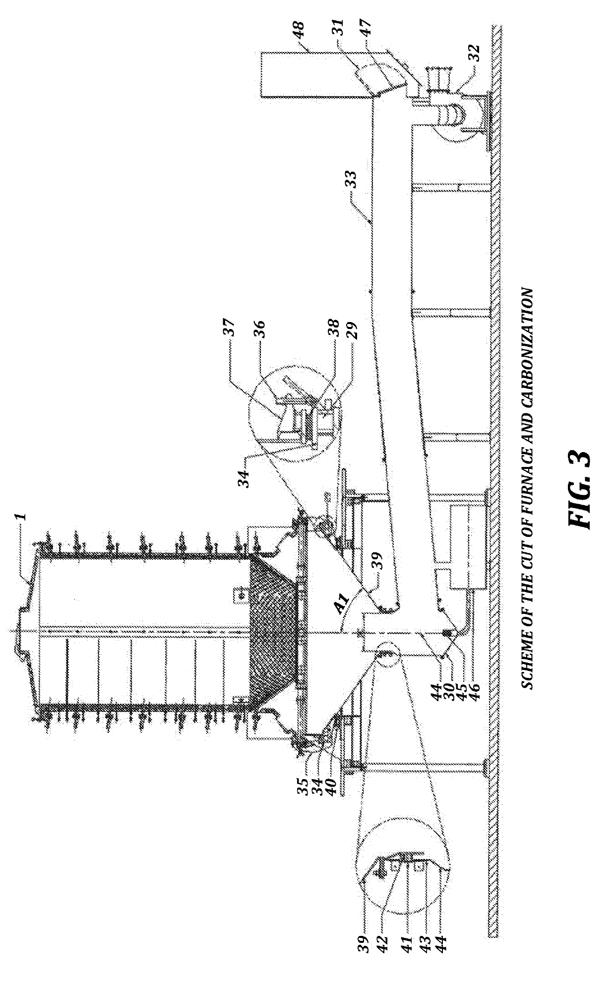
Thus, not only the control strategy becomes more troublesome, but there is great potential for the occurrence of problems such as condensation, incrustation and obstruction because of the condensable gases arising from coal production, such as tar and pyroligneous.
As in the same reactor simultaneously occurs pyrolysis, cooling and drying, there is not possibility to build a tank that specifically meets each of these steps.
One possibility would be a gasometer for gases storage that will be circulated, but due to the presence of condensables, this idea can not be as viable as simple combustion of an initial amount of wood.
The processes shown in the present state of art, therefore, flaws in their design and conception and they do not offer complete solutions to the problem of industrial production of charcoal.
All constructions use the furnace for the production of charcoal as a container for promoting coal cooling and there is not a solution comprising technical, economic, energetic and environmental viability simultaneously.
Masonry furnaces for the production of charcoal have as a major drawback the fact that their high time for converting biomass into charcoal, as mentioned above, between 12 and 14 days.
This high time is partly due to bad distribution of gas flow inside the furnace.
Coupled with the absence of proper control of temperature and oxygen supply, in the “rabo quente” furnace there are presence of cracks and holes in the masonry wall that result in frequent explosions and collapse of the furnaces, with consequent financial loss.

Method used


Image

  • Industrial process using a forced-exhaust metal furnace and mechanisms developed for simultaneously producing coal, fuel gas, pyroligneous extract and tar
  • Industrial process using a forced-exhaust metal furnace and mechanisms developed for simultaneously producing coal, fuel gas, pyroligneous extract and tar
  • Industrial process using a forced-exhaust metal furnace and mechanisms developed for simultaneously producing coal, fuel gas, pyroligneous extract and tar

Examples


application examples

[0101]Below, it will be shown a series of possible configurations for the invention, which aim illustrate its several uses. And, although it can be exemplified by, it is not limited to the examples that follow.

example 1

[0102]The industrial furnace of production of charcoal with capacity for 35 m3 can be loaded by the upper hole with wood cavacos, average granulometry between 100 and 120 mm. The furnace, already with the cover placed and locked, is placed on the carbonization system and locked on the movable support base. The exhauster is then switched on and the ignition on specific points, with ember, starts. The carbonization control by the opening and closing of the holes follows in order to provide energy for the endothermic phase. The process ends in about 3 hours, producing 2400 kg of charcoal with gravimetric yield of 33%.

example 2

[0103]The industrial furnace for charcoal production with a capacity of 35 m3 can be loaded by the upper hole with wood small logs, average size of 200 mm. The furnace already with the cover placed and locked, is placed on the carbonization system and locked on the movable support base. The exhauster is then switched on and the ignition on specific points, with ember, starts. The carbonization control by the opening and closing of the orifices follows in order to provide energy for the endothermic phase. The process ends in about 5 hours, producing 2800 kg of charcoal with gravimetric yield of 35%.


PUM

PropertyMeasurementUnit
flow velocityaaaaaaaaaa
flow rateaaaaaaaaaa
flow rateaaaaaaaaaa

Abstract

This patent of invention is related to a process and a furnace developed for production of charcoal with recovery of gases, tar and pyroligneous extract. The unity system is composed by a metallic furnace, a loading platform, a carbonization platform and unloading platform. For continuous generation of gases, the process operates with multiple carbonization platforms and one or more furnaces for carbonization platform. The furnace is provided with air inputs in strategic side points and mechanism for relieving pressure. The carbonization system is composed by an exhauster, special pipes for conducting the gases, and devices for the recovery of condensable. The gases generated in the process are directed to a burner, a gasifier or directly in a boiler to generate thermal and / or electrical energy. The technology presents, exclusively, a gravimetric yield in fuel gas superior to 60% and a productivity on charcoal above 800 kg / h, so that each operating cycle of the furnace takes less than 5 hours. The coal is discharged hot, after carbonization and loaded on wooden billets immediately after unloading. The process combines technical, economic, operational, and environmentally viable solutions.

Description

FIELD USE[0001]This patent relates to a process and a furnace designed for charcoal production with the recovery of the gases, tar and pyroligneous extract.PRIOR ART[0002]This invention relates to a process and a furnace for industrial production of charcoal and recovery of the gases generated in the process, in order to solve the problem inherent to carbonization process as implemented today by most charcoal. In Brazil, most of the charcoal production, around 70% comes from the traditional charcoal kilns of brick kilns, said “rabo-quente furnace.” These furnaces have a low percentage yield by weight in the conversion of biomass into charcoal and have high long production cycles. Typically they are spending five days to carbonize biomass and 7 days to complete cooling, i.e. between the loading and unloading are used about 12 to 14 days.[0003]In the traditional process for producing coal in brick kilns type “Rabo-quente”, wood and coal are respectively loaded and unloaded manually, s...

Claims


Application Information

Patent Timeline
Patent Type & Authority Applications(United States)
IPC IPC(8): C10B27/02C10B1/04F01K11/02C10B53/02C10B49/02C10B41/00C10B7/06C10B17/00C10B39/04C10B39/14C10B33/04C10B3/00
CPCC10B1/04Y02E50/14F01K11/02C10B53/02C10B49/02C10B41/00C10B27/02C10B7/06C10B17/00C10B39/04C10B39/14C10B33/04C10B3/00C10B15/00Y02E50/10
Inventor VICINTIN, RICARDO ANTONIODE OLIVEIRA VILELA, ADRIANAURBANO ALVES, JOSEPACCELI DA SILVA E SOUZA, THALIS
Owner BOCAIUVA MECANICA
Why Eureka
Try Eureka