Magnetic tunnel junction, spintronics device using same, and method for manufacturing magnetic tunnel junction
- Summary
- Abstract
- Description
- Claims
- Application Information
AI Technical Summary
Benefits of technology
Problems solved by technology
Method used
Image

Examples
first embodiment
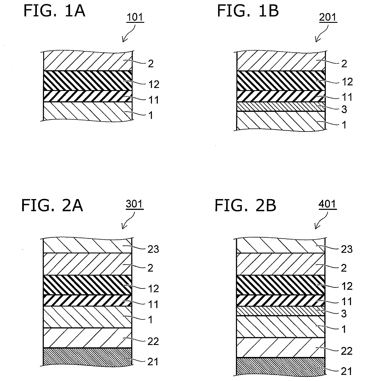
[0056]A MTJ film first embodiment 101 which is the basic structure of a first embodiment is shown in FIG. 1A. The MTJ film first embodiment 101 has a multilayer film structure; and a first magnetic layer 1, a first insulating layer 11, a second insulating layer 12, and a second magnetic layer 2 are stacked in order from the bottom. Either of the first magnetic layer 1 and the second magnetic layer 2 may be a fixed magnetic layer or a free magnetic layer. Also, the magnetization direction may be either a film in-plane direction or a film out-of-plane direction. The fabrication method and the effects of the structure of the MTJ film first embodiment 101 will now be described.
[0057]The first magnetic layer 1 is, for example, a layer made of Co—Fe—B formed by physical vapor deposition such as sputtering, vapor deposition, etc. The Co—Fe—B has an amorphous structure at this stage. It is sufficient for the composition of Co and Fe to be Co1-nFen (0≤n≤1); and the composition of Co and Fe i...
second embodiment
[0066]A second embodiment is shown as a MTJ film second embodiment 201 in FIG. 1B and will now be described. The MTJ film second embodiment 201 is the MTJ film first embodiment 101 in which a magnetic insertion layer 3 is newly provided between the first magnetic layer 1 and the first insulating layer 11. Otherwise, a structure, a composition, and a manufacturing method equivalent to those of the MTJ film first embodiment 101 can be used. The magnetic insertion layer 3 is a thin insertion layer made of Co1-mFem (03 has the effect of promoting the crystallization of both the first insulating layer 11 and the second insulating layer 12, and causes the improvement of the TMR ratio. It is favorable for the film thickness of this layer to be thinner than the first magnetic layer 1, e.g., 0.1 to 1.5 nm. The magnetic insertion layer 3 can be made using the same technique as Co—Fe—B such as sputtering, vacuum vapor deposition, etc. To improve the flatness of the magnetic insertion layer 3, ...
third embodiment
[0067]As shown typically as a MTJ film third embodiment 301 in FIG. 2A, a third embodiment is the MTJ film first embodiment 101 in which a lower structure of the first magnetic layer 1 and an upper structure of the second magnetic layer 2 are newly provided. First, a substrate 21 is provided; and an underlayer structure layer 22 is provided on the substrate 21. The MTJ film first embodiment 101 is provided on the underlayer structure layer 22. Also, an upper structure layer 23 is provided on the MTJ film first embodiment 101.
[0068]It is desirable for the substrate 21 to be flat and homogeneous. As the material, for example, a Si-based material such as Si, Si having a thermal oxide film (Si / SiO2), SiN, SiC, etc., a compound semiconductor such as GaAs, etc., or an oxide crystal such as MgO, MgAl2O4, sapphire, etc., can be used.
[0069]The underlayer structure layer 22 is provided between the substrate 21 and the first magnetic layer 1, is used as an electrode layer on the lower side, an...
PUM
 Abstract
Description
Claims
Application Information