Beam control apparatus

a control apparatus and beam technology, applied in lighting and heating apparatus, lighting device details, instruments, etc., can solve the problems of poor penetration performance and obstacle bypassing capacity, inability to meet communication needs, etc., to achieve high requirements, simple structure, and control structure

Active Publication Date: 2020-04-02
XU WEIKE
View PDF0 Cites 1 Cited by
  • Summary
  • Abstract
  • Description
  • Claims
  • Application Information

AI Technical Summary

Benefits of technology

[0039]Based on the above technical solutions, the present invention implements a beam control apparatus and has the following prominent technical effects: (1) all movable components of the present invention are designed as completely-closed structures, so that the maintenance is avoided, and the problems of dust entering a bearing or a rotor, failure of lubricating fluid, etc. in the existing servo control can be avoided; (2) the present invention is simple in structure and can be miniaturized; (3) the beam deflection angle of the present invention is not actually limited, and the application occasions with relatively high requirements for the beam directing angle range can be satisfied; (4) since the control structure is simple, and the relative weight is light, the beam control apparatus of the present invention is low in power consumption while working and applicable to the application occasions sensitive to the power consumption such as mobile communications; (5) the beam control apparatus of the present invention could be controlled by the pulse width modulation (PWM) mode, so that the driving actuators could be simple, and the static frictions can be overcome due to the characteristics of the pulse width modulation mode; and (6) the emergent beam in the beam directing component of the present invention can be emitted in various ways, so that the universality and flexibility are good.

Problems solved by technology

At present, the laser beam direction control apparatuses used in these fields are all based on the traditional motor servo control and are difficult in miniaturization and relatively high in maintenance cost.
If the frequency is higher, the penetration performance and the obstacle bypassing capacity become poorer and are even similar to those of the visible light that requires a rectilinear pathway.
If the frequency is lower, the bandwidth is too narrow to support the communication needs.
To further increase the bandwidth, a technology for a single user to share multiple channels is even provided, which is limited by the density of access users, and the increase of the bandwidth is limited; and moreover, the method for increasing the communication bandwidth within the existing technological framework has negative effects of worsening an electromagnetic environment, aggravating the electromagnetic pollution and making the adverse effect of the wireless communication on the health of the human body increasingly acute.
However, the penetration performance and the obstacle bypassing capacity of radio waves of the wavelengths are poor and a rectilinear pathway is almost required between a mobile terminal and a signal base station.
If the existing signal transmission mode of large-angle broadcasting continues to be used, it will be even worse for the electromagnetic environment that is already severe at present.
It can be said that the existing wireless communication technologies such as mobile phones, WIFI and the like face the bottleneck of communication bandwidth.
However, since the electromagnetic waves with higher frequency are poorer in penetration performance and the obstacle bypassing capacity, a visible pathway is required between the mobile terminal and the signal base station or between two terminals.
An output end of each optical fiber is controlled by an inching control unit to move on a focal plane of the lens, thereby controlling the direction of light beams emitted from the lens; however, since the outgoing end of the optical fiber needs to be located on the focal plane of the lens, the scope of the light beam direction controlled by the method is limited to a certain extent, and a divergence angle of the light beam is also difficult to control accurately.
Each prism needs independent servo control, so that the system is complicated and difficult to be miniaturized.
However, restricted by free space optical interconnection technologies, no commercial product for public use exists at present.

Method used


Image

  • Beam control apparatus
  • Beam control apparatus
  • Beam control apparatus

Examples


embodiment i

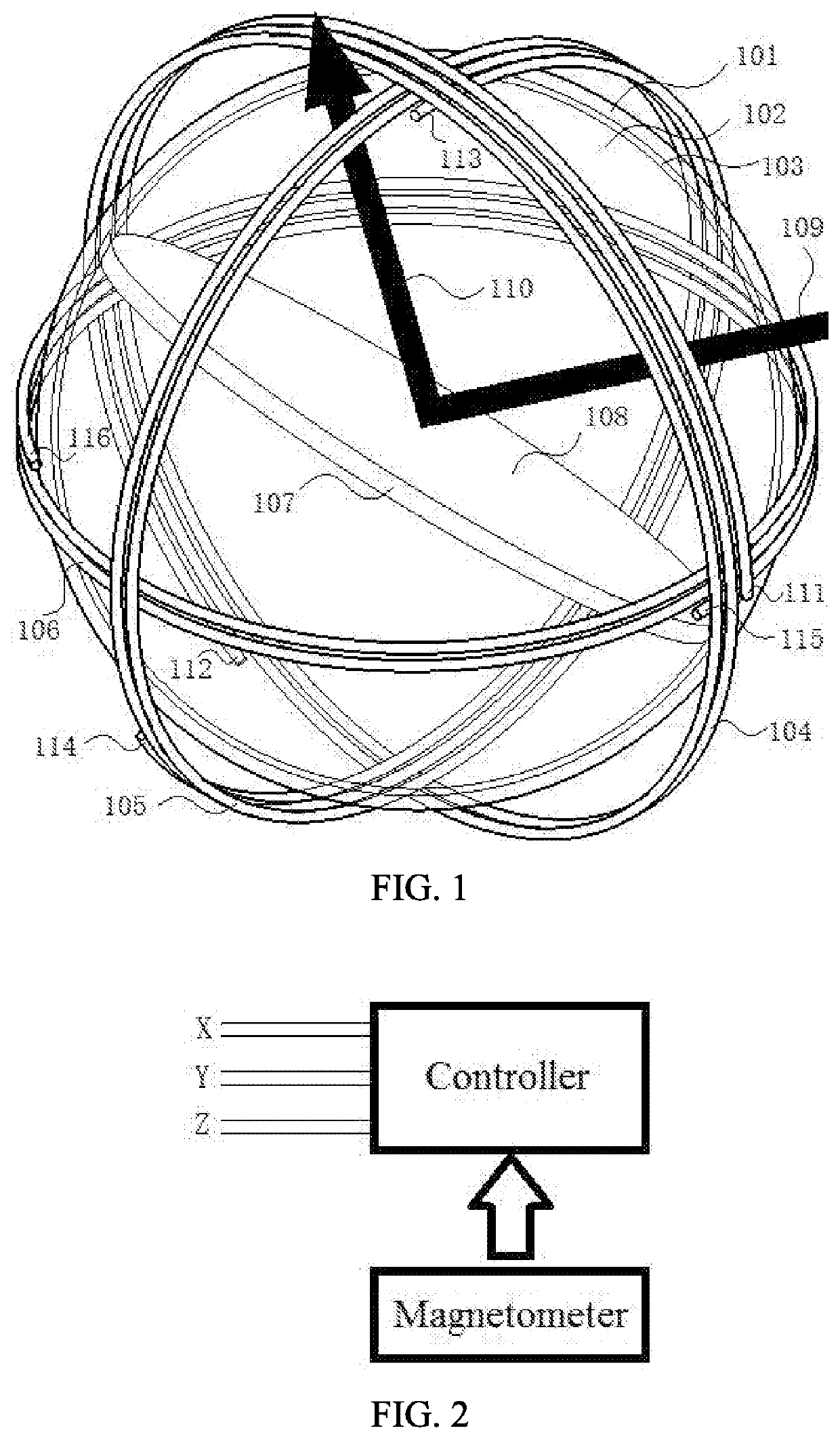
[0056]As shown in FIG. 1, a beam control apparatus includes a beam directing component and an electromagnetic field control component. To clearly show each portion, FIG. 1 is not drawn strictly according to a proportion. The electromagnetic field control component consists of a transparent spherical shell 101, a conductive coil 104, a conductive coil 105 and a conductive coil 106. The conductive coil 104, the conductive coil 105 and the conductive coil 106 are fixed on the outer side of the transparent spherical shell 101. The inner side of the transparent spherical shell 101 is a spherical cavity of the electromagnetic field control component. The beam directing component consists of a transparent spherical shell 102, a permanent magnet disc 107 and a reflection surface 108. The permanent magnet disc 107 and the reflection surface 108 are fixed with the transparent spherical shell 102.

[0057]The transparent spherical shell 102 is located inside the transparent spherical shell 101. T...

embodiment ii

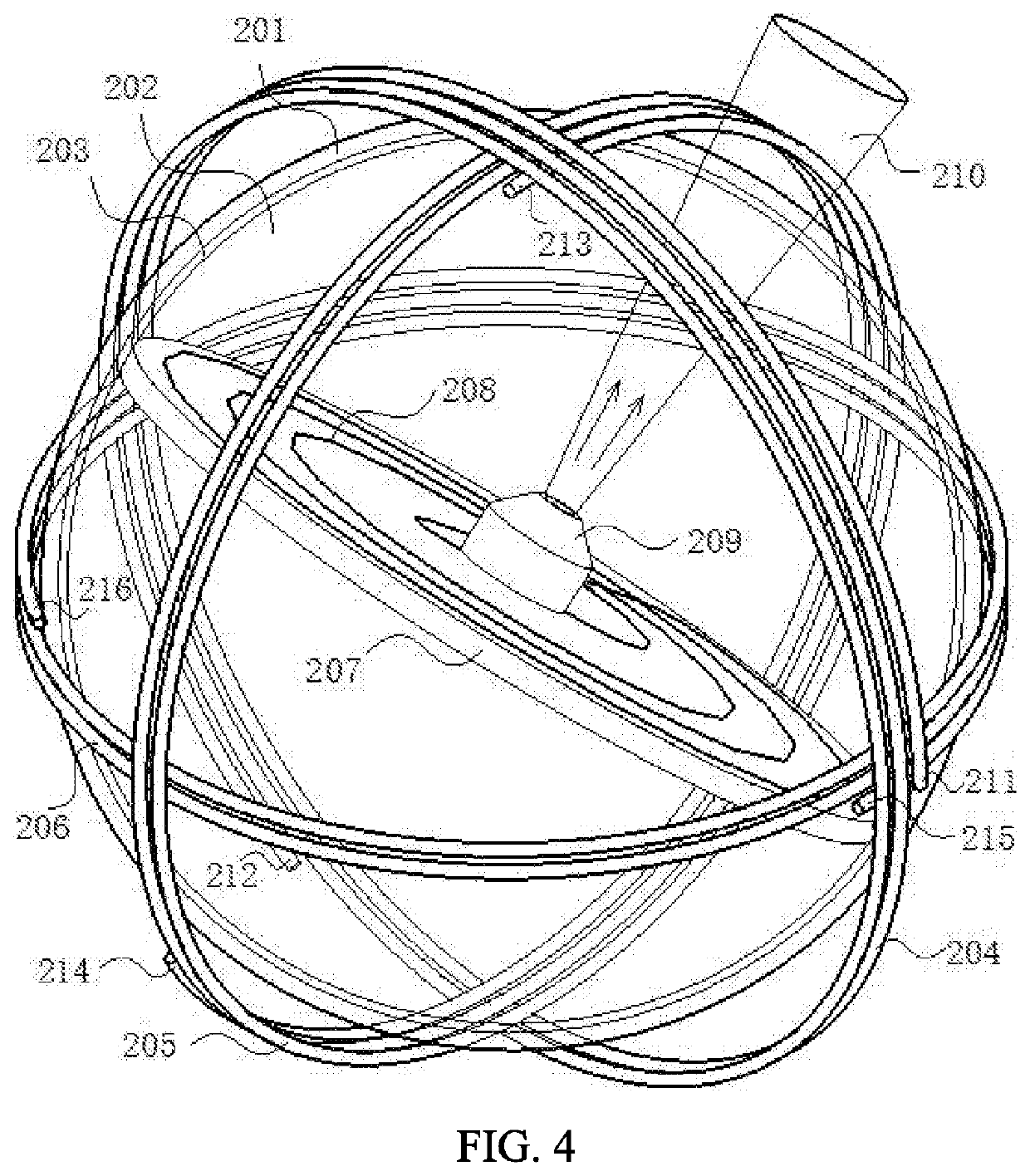
[0074]As shown in FIG. 4, a beam control apparatus includes a beam directing component and an electromagnetic field control component. To clearly show each portion, FIG. 4 is not drawn strictly according to the proportion. The electromagnetic field control component consists of a transparent spherical shell 201, a conductive coil 204, a conductive coil 205 and a conductive coil 206. The conductive coil 204, the conductive coil 205 and the conductive coil 206 are fixed on the outer side of the transparent spherical shell 201. The inner side of the transparent spherical shell 201 is a spherical cavity of the electromagnetic field control component, and the beam directing component is located inside the spherical, cavity. The beam directing component consists of a transparent spherical shell 202, a permanent magnet disc 207, a magnetic field induction coil 208 and a luminous element 209. The permanent magnet disc 207 is fixed inside the transparent spherical shell 202. The magnetic fie...

embodiment iii

[0087]As shown in FIG. 6, a beam control apparatus includes a beam directing component and an electromagnetic field control component. To clearly show each portion, FIG. 6 is not drawn strictly according to the proportion.

[0088]The electromagnetic field control component consists of a transparent spherical shell 301, a conductive coil 304, a conductive coil 305 and a conductive coil 306. The inner side of the transparent spherical shell 301 is a spherical cavity of the electromagnetic field control component, and the beam directing component is located in the spherical cavity. The transparent spherical shell 301 of the electromagnetic field control component is made of quartz glass with an outer diameter of 3.0 mm and an inner diameter of 2.7 mm. The conductive coil 304, the conductive coil 305 and the conductive coil 306 are fixed on the outer side of the transparent spherical shell 301. Moreover, planes where the three conductive coils are located pass the sphere center of the tra...


PUM


Abstract

A beam control apparatus consists of an electromagnetic field control component, which has a spherical cavity encircled by a transparent spherical shell, and a beam directing component which is spherical in shape and located in the spherical cavity. The two components can rotate relative to each other. A clearance between the two components could be filled with lubricant. The beam directing component has a magnetic moment or an electric dipole moment. A controller controls a magnetic field or an electric field in the spherical cavity of the electromagnetic field control component to exert a torque on the beam directing component to control a direction of the beam directing component, thereby controlling a direction of an emergent beam. The present invention is a new terminal technology for free space optical communications, laser scanning, unmanned driving, laser beam driving and location identification.

Description

CROSS-REFERENCE TO RELATED APPLICATIONS[0001]This application is a continuation of International Patent Application No. PCT / CN2018 / 091886 with a filing date of Jun. 19, 2018, designating the United States, now pending, and further claims priority to Chinese Patent Application No. 201710553949.8 with a filing date of Jul. 9, 2017. The content of the aforementioned applications, including any intervening amendments thereto, are incorporated herein by reference.TECHNICAL FIELD[0002]The present invention relates to the field of beam direction control, and particularly relates to the field of free space optical communications.BACKGROUND OF THE PRESENT INVENTION[0003]The technology for controlling the directive emission of beams has important applications in various fields. For example, in the fields of automatic driving and laser surveying and mapping, a laser scanning technology is one of the key technologies. The work to be accomplished by the laser scanning is to control the direction...

Claims


Application Information

Patent Timeline
Patent Type & Authority Applications(United States)
IPC IPC(8): G02B26/10G02B26/08H04B10/11
CPCG02B26/106H04B10/11G02B26/101G02B26/108G02B26/0816G02F1/0081G02F1/29G02F1/292F21V14/00G02F1/00
Inventor XU, WEIKE
Owner XU WEIKE
Why Eureka
Try Eureka