Tubular pecvd device for bifacial perc solar cell

a solar cell and tube-type technology, applied in the field of solar cells, can solve the problems of limited photoelectric conversion efficiency of the battery, less than ideal passivation effect of the film, low uptime, etc., and achieve the effect of improving the photoelectric conversion efficiency of the solar cell, reducing production costs, and expanding the scope of application

Inactive Publication Date: 2021-04-15
GUANGDONG AIKO SOLAR ENERGY TECH CO LTD +1
View PDF0 Cites 0 Cited by
  • Summary
  • Abstract
  • Description
  • Claims
  • Application Information

AI Technical Summary

Benefits of technology

[0011]The objective of the present invention is to provide a bifacial tube-type PERC solar cell which can absorb sunlight on both surfaces, has high photoelectric conversion efficiency, high appearance quality, and high EL yield, and could solve the problems of both scratching and undesirable deposition.
[0012]Another objective of the present invention is to provide a method of preparing the bifacial tube-type PERC solar cell, which is simple, can be carried out at a large scale, and is compatible with existing production lines. The solar cells produced have high appearance quality and high EL yield, and could solve the problems of both scratching and undesirable deposition.
[0013]Yet another objective of the present invention is to provide a device for producing the bifacial tube-type PERC solar cell. The device has a simple structure, is able to lower production cost, and has large capacity and yield. The solar cells produced have high appearance quality and high EL yield, and could solve the problems of both scratching and undesirable deposition.

Problems solved by technology

Therefore, a disadvantage of the plate PECVD system is that the combination of layers in the composite film cannot be flexibly adjusted; thus, it is impossible to optimize the passivation effect of the rear surface film, which limits the photoelectric conversion efficiency of the battery.
In addition, the plate PECVD system employs an indirect plasma method, which gives a less than ideal passivation effect of the film.
The plate PECVD system also has other disadvantages including low uptime and long maintenance time, which affects its capacity and yield.
Despite the above, the cells produced by tubular PECVD technology have poor appearance quality and low electroluminescence (EL) yield due to contradictive problems of undesirable deposition and scratching; these drawbacks prevent the application of this technology in mass production.
On the other hand, when using tubular PECVD to form the rear surface film of a PERC cell, scratching and undesirable coating would seriously affect the pass rate of the cell product.
The problems are as follows: 1. during the deposition of the rear surface film, undesirable coating would take place at the edges of the front surface of the cell.
As the PERC cell is coated on both sides, the coating at the edges of the front surface would be relatively thick; consequentially, graphite boat marks and color difference appear at the edges of the front surface of the cell, affecting the appearance quality; 2. when being inserted into the graphite boat, the front surface of the silicon wafer would be in contact with the graphite boat wall, scratching the p-n junctions at the front surface; as a result, scratches would be present during the EL test, and the electrical performance of the cell would be affected.

Method used


Image

  • Tubular pecvd device for bifacial perc solar cell
  • Tubular pecvd device for bifacial perc solar cell
  • Tubular pecvd device for bifacial perc solar cell

Examples


first embodiment

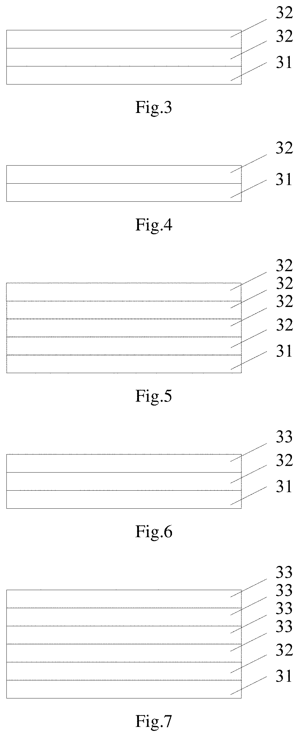
[0090]In the rear surface composite film shown in FIG. 3, the bottom layer 31 of the rear surface composite film 3 is an aluminum oxide film; the top layer 32 of the rear surface composite film is composed of a silicon oxynitride film and a silicon nitride film.

second embodiment

[0091]In the rear surface composite film shown in FIG. 4, the bottom layer 31 of the rear surface composite film is an aluminum oxide film; the top layer 32 of the rear surface composite film is a silicon nitride film.

third embodiment

[0092]In the rear surface composite film shown in FIG. 5, the bottom layer 31 of the rear surface composite film is an aluminum oxide film; the top layer 32 of the rear surface composite film is composed of a silicon dioxide film, a silicon oxynitride film A, a silicon oxynitride film B, and a silicon nitride film.

[0093]Referring to FIGS. 6, 7, and 8, the bottom layer 31 of the rear surface composite film is a silicon dioxide film; the middle layer 32 of the rear surface composite film is an aluminum oxide film; the top layer 33 is composed of one or more films selected from the group consisting of a silicon dioxide film, a silicon oxynitride film, and a silicon nitride film.


PUM

PropertyMeasurementUnit
depthaaaaaaaaaa
diameteraaaaaaaaaa
angle of inclinationaaaaaaaaaa

Abstract

The present invention discloses a tubular PECVD device for bifacial PERC solar cell. The present invention bifacial PERC solar cell has high photoelectric conversion efficiency, high appearance quality, and high EL yield, and could solve the problems of both scratching and undesirable deposition.

Description

CROSS-REFERENCE TO RELATED APPLICATIONS[0001]This application is a continuation of U.S. application Ser. No. 16 / 345,751, filed Apr. 29, 2019, which is a U.S. national stage application of the International Patent Application No. PCT / CN2017 / 086030, filed May 25, 2017, which claims the benefit of Chinese Patent Application No. 201710353392.3, filed May 18, 2017, all of which are incorporated herein by reference in their entireties.FIELD OF THE INVENTION[0002]The present invention relates to the field of solar cells, and in particular to a bifacial tube-type PERC solar cell, a preparation method thereof, and production device therefor.BACKGROUND OF THE INVENTION[0003]A crystalline silicon solar cell is a device that effectively absorbs solar radiation energy and converts light energy into electrical energy through the photovoltaic effect. When sunlight reaches the p-n junction of a semiconductor, new electron-hole pairs are formed. Under the action of the electric field at the p-n junc...

Claims


Application Information

Patent Timeline
Patent Type & Authority Applications(United States)
IPC IPC(8): H01L31/068C23C16/30C23C16/34C23C16/40H01L31/0224H01L31/0236
CPCH01L31/0684C23C16/308C23C16/345H01L31/02363C23C16/403H01L31/022425C23C16/402H01L31/0236H01L31/18C30B33/00C23C16/50C23C16/458C23C16/56H01L31/1876H01L31/068H01L31/1868Y02E10/547Y02P70/50H01L31/0392H01L31/036H01L21/02274H01L21/02178H01L21/02164H01L21/0217H01L21/324H01L21/67017H01L21/673H01L21/67265H01L21/67294H01L31/186C23C16/54H01J37/32743H01J37/32899H01L21/67754H01L21/67763
Inventor FANG, JIEBINLIN, KANG-CHENGLAI, CHUN-WENHE, NAILINYIN, WENJIEHO, TA-NENGCHEN, GANG
Owner GUANGDONG AIKO SOLAR ENERGY TECH CO LTD
Why Eureka
Try Eureka