Hollow zeolites catalysts for the production of alkl aromatic compounds from aromatic hydocarbons and olefins

a technology of hollow zeolites and catalysts, which is applied in the direction of inorganic chemistry, pentasil aluminosilicate zeolite, molecular sieve catalysts, etc., can solve the problems of poor dispersion of catalytic material on the surface of zeolite, deactivation, stability, and leaching of catalysts, and achieves the effect of increasing catalytic stability and efficiency

Inactive Publication Date: 2021-07-15
SABIC GLOBAL TECH BV
View PDF0 Cites 0 Cited by
  • Summary
  • Abstract
  • Description
  • Claims
  • Application Information

AI Technical Summary

Benefits of technology

[0005]A solution to the problems associated with the costs, deactivation, and degradation of alkylation catalysts has been discovered. The solution lies in the production of alternatives to the aforementioned acidic zeolite catalysts. In particular, it was surprisingly found that a metal nanostructure, an oxide or an alloy thereof, with a Lewis acid active site encapsulated in an inert or substantially inert zeolite support was capable of catalyzing the alkylation reaction of an aromatic hydrocarbon and olefin to form an alkyl aromatic compound, preferably an alkylation reaction to form ethylbenzene from benzene and ethylene. Alternatively, the alkylation reaction can be used to form isopropylbenzene (cumene) from benzene and propylene. Notably, the inert hollow zeolite support (i.e., a support that is substantially or completely non-reactive with the reactants and/or reactive intermediates, such as a support that is substantially or completely devoid of active acidic sites) has a peripheral shell with an exterior surface and an interior surface that defines and encloses a hollow space within the interior of the shell, and the metal nanos

Problems solved by technology

However, these catalysts suffer from deactivation, stability, and leaching of the catalytic material.
By way of example, the catalytic material can be smaller than the pores of the zeolite allowing the catalytic material to diffuse through the pore, which diminishes the stability of the catalyst.
Other problems associa

Method used


Image

  • Hollow zeolites catalysts for the production of alkl aromatic compounds from aromatic hydocarbons and olefins
  • Hollow zeolites catalysts for the production of alkl aromatic compounds from aromatic hydocarbons and olefins
  • Hollow zeolites catalysts for the production of alkl aromatic compounds from aromatic hydocarbons and olefins

Examples


example 1

Synthesis of Fe(III)2O3 / Hollow-Silicalite-1 Catalyst Material

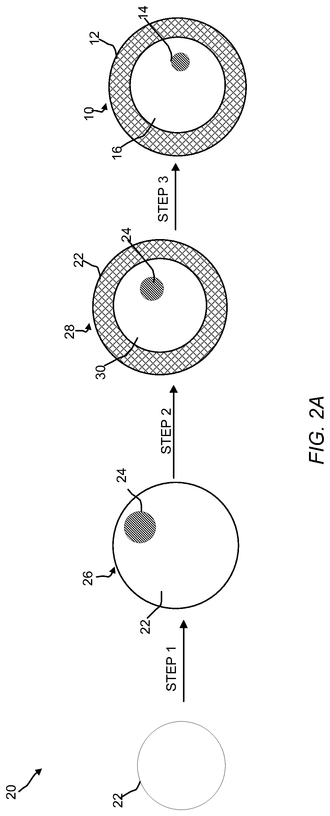
[0053]Silicalite-1 is obtained by mixing tetraethylorthosilicate (TEOS, 98% purity, Sigma-Aldrich®, USA) and tetrapropylammonium hydroxide (TPA(OH), 1.0 M, in H2O, Sigma-Aldrich®, USA) with water. The gel composition is SiO2: 0.4 TPA(OH): 35 H2O. Then, the mixture is transferred into a Teflon-lined autoclave and heated at 170° C. under static condition for 3 days. The solid was recovery by centrifugation and washed with water, which was repeated 3 times. The resulting solid was dried overnight at 110° C. and then calcined at 525° C. in air for 12 h. Subsequently, the zeolite was treated under vacuum (0.1 to 1 mbar) at 300° C. for 10 hours. Then, dry impregnation of iron nitrate on the zeolite surface was carried out (3 wt. % of Fe, CFe(NO3)3 solution=0.5 mol. L−1) in water. After impregnation, the impregnated zeolite was dried and then calcined (2 h under air, 400° C., 1° C. / min) in order to obtain a metal oxide which was ...

example 2

Characterization of Fe2O3 in Hollow Silicalite-1

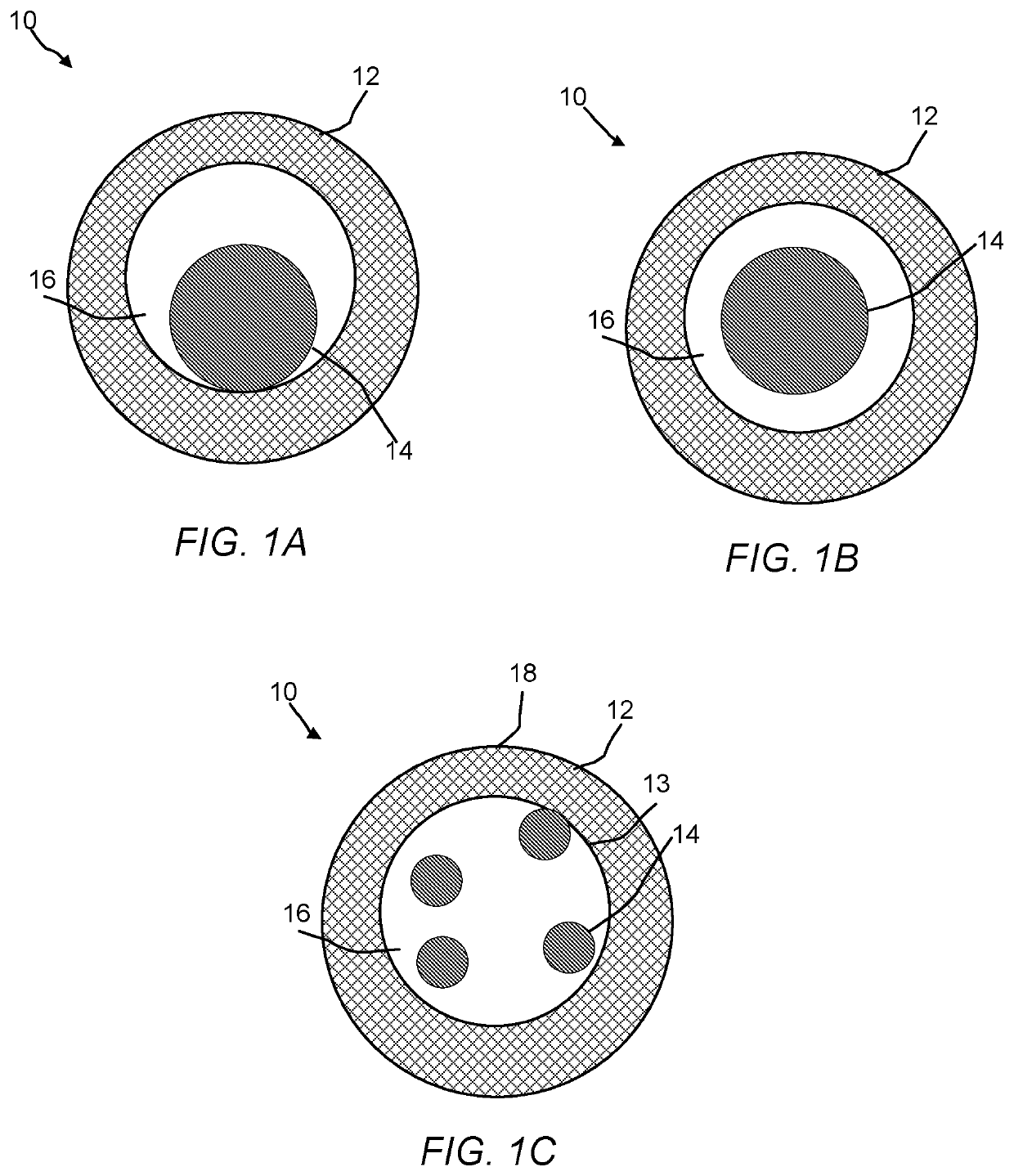
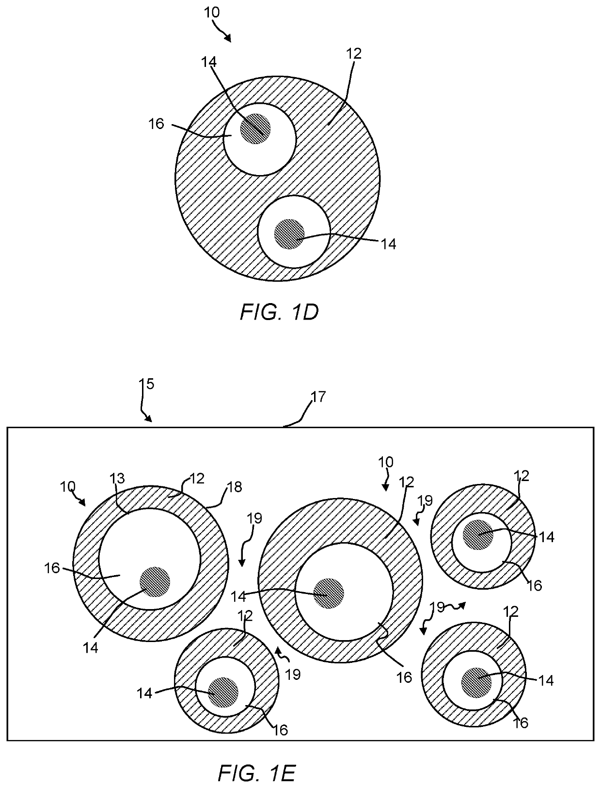
[0054]Transmission Electron Microscopy (TEM) analysis was performed on the inventive sample from Example 1 using a Titan G2 80-300 kV transmission electron microscope operating at 300 kV (FEI™, USA) equipped with a 4 k×4 k CCD camera, a GIF Tridiem filter (Gatan, Inc., USA), and an Energy dispersive X-ray (EDAX) detector. FIGS. 4A and 4B are TEM images of the catalyst of Example 1 at a scale of 200 nm and 20 nm. From the TEM, it was determined that regular hexagonal shaped nanoparticles of hollow zeolite with an average dimension of 50 to 60 nm were formed. The wall thickness of the hollow silicalite-1 zeolite was about 15 nm whereas the cavity was about 30 nm. Nanoparticles of iron were not observable within the microscope resolution, but were detected by EDAX (See, FIG. 5). It was determined that by using this process of making the metal nanostructure / hollow zeolite, a high homogeneity of hollow zeolite was obtained in terms of size ...

example 3

Production of Ethylbenzene from Ethylene and Benzene

[0055]The catalyst (300 g) from Example 1 or a comparative catalyst (H-ZSM-5, Si / Al=30) and benzene (10 mL) were introduced into a 100 mL PARR autoclave reactor. Then, the pressure was increased to 10 bar with pure ethylene. The reactor was stirred and the temperature was increased to 250° C. After 24 h, the reaction was cooled and the liquid phase was analyzed by using an Agilent Technologies (USA) GC-MS (Agilent 7890b with a FID detector and HP 5MS UI columns, 0.25 micrometer and a Agilent 5977A Mass spectrometer). The benzene conversion for the comparative catalyst 15% and the conversion for the Fe-silicate-1 catalyst of the present invention was 9%. FIG. 6 shows a high selectivity in ethylbenzene (SelecEB) of 90% for the Fe-Silicalite-1 catalyst. In FIG. 6, the peak at 2.2 min. was benzene and the peak at 4.3 min. was ethylbenzene. FIG. 7 shows the comparative catalyst with the formation with ethylbenzene and the by-product met...


PUM

PropertyMeasurementUnit
Temperatureaaaaaaaaaa

Abstract

Supported catalysts, methods of making and using are described herein. A supported catalyst can include a metal nanostructure, an oxide, or an alloy thereof, having a Lewis acid active site capable of catalyzing the formation of an alkyl aromatic compound from an aromatic hydrocarbon and an olefin, and an inert hollow zeolite support. The inert hollow zeolite support has a peripheral shell with an exterior surface and an interior surface that defines and encloses a hollow space within the interior of the shell, where the metal nanostructure, or an oxide or an alloy thereof is comprised in the hollow space.

Description

CROSS REFERENCE TO RELATED APPLICATIONS[0001]This application claims the benefit of priority of U.S. Provisional Patent Application No. 62 / 297,482 filed Feb. 19, 2016, and U.S. Provisional Patent Application No. 62 / 378,478 filed Aug. 23, 2016. The entire contents of each of the above-referenced disclosures are specifically incorporated herein by reference without disclaimer.BACKGROUND OF THE INVENTIONA. Field of the Invention[0002]The invention generally concerns a catalyst for the production of alkyl aromatic compounds from aromatic hydrocarbons and olefins. In particular, the invention concerns a catalyst that includes a metal nanostructure or an oxide or an alloy thereof having a Lewis acid active site capable of catalyzing alkyl aromatic formation from aromatic hydrocarbons and olefins, and a hollow zeolite support having a peripheral shell with an exterior surface and an interior surface that defines and encloses a hollow space within the interior of the shell, wherein the meta...

Claims


Application Information

Patent Timeline
IPC IPC(8): B01J29/80B01J29/035C07C2/66
CPCB01J29/80B82Y30/00C07C2/66B01J29/0356B01J29/061B01J29/405B01J29/46B01J29/48B01J29/7057B01J29/7615B01J29/7815B01J35/002B01J35/0086B01J35/023B01J35/026C01B39/026B01J2229/186B01J2229/22B01J2229/38C01B37/02C01B39/087C01B39/40C01B39/46C07C2529/035C07C15/073B82Y40/00C07C15/085C07C2529/80
Inventor RAVON, UGOBIAUSQUE, GREGORYALBAHILY, KHALID
Owner SABIC GLOBAL TECH BV
Why Eureka
Try Eureka