
Method and device for processing active microcrystalline fiber by magnetic field induction and laserit

a technology of active microcrystalline fiber and magnetic field induction, which is applied in the field of special optical fibers, can solve the problems of limiting the further improvement of laser output power, low doping concentration, and improving the output power of fiber lasers, and achieves accurate control of crystallization area, high luminescence efficiency, and high doping concentration

Active Publication Date: 2022-05-12
SHANGHAI UNIV
View PDF0 Cites 0 Cited by
  • Summary
  • Abstract
  • Description
  • Claims
  • Application Information

AI Technical Summary

Benefits of technology

The patent describes a laser processing technology that allows for precise control over crystalline areas using small laser action spots. Additionally, the technology also allows for control of grain growth through the use of a magnetic field. The resulting active microcrystalline fibers have high doping concentration, luminescence efficiency, fluorescence life, and conversion efficiency, making them ideal for use in fiber lasers and amplifiers.

Problems solved by technology

However, with the continuous improvement of the output power of fiber laser, the thermal effect, nonlinear effect, photon darkening effect and mode instability seriously restrict the improvement of the output power of fiber laser.
The doping concentration is low, which has approached the limit of quartz matrix fiber, and restricts the further improvement of laser output power.
The transmission loss in the microcrystalline fiber is mainly due to the light scattering caused by the grain.
However, Yb:YAG crystal has a fixed melting point and is not easy to be drawn into fiber, so the thermal effect is large.
In the published patent literature, the application number CN104609722A has proposed a preparation method of tube-melt co-pull bismuth doped fiber, It is not suitable for material preparation with high heat treatment temperature and has limitations.

Method used


Image

  • Method and device for processing active microcrystalline fiber by magnetic field induction and laserit
  • Method and device for processing active microcrystalline fiber by magnetic field induction and laserit

Examples


example 1

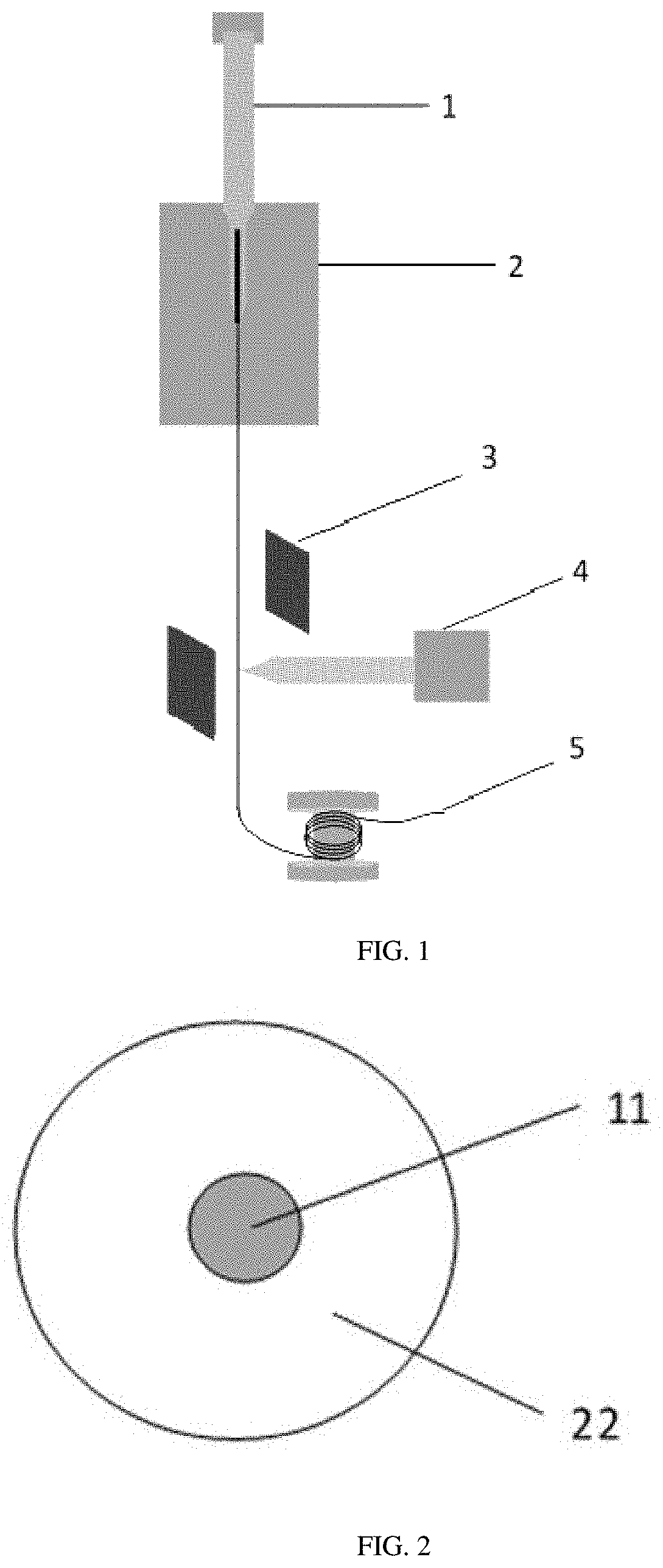
[0041]As shown in FIG. 1, a method for processing active microcrystalline fiber by magnetic field induction and laserit, the specific steps are: Yb:YAG crystals with a doping concentration of 10 at % were processed into micron rods, their surfaces were polished, and the rods were inserted into the cleaned and dried quartz sleeve to make prefabricated rods. The prefabricated rod is fixed on the laser drawing furnace by aluminum fixture for wire drawing, in wire drawing; the doped fiber drawn is made to pass through an alternating magnetic field in an uncoated state. The two magnetic poles of the alternating magnetic field are vertically placed on both sides of the fiber, and the fiber coincide with the central axis of the two magnetic poles. The magnetic field intensity is 0.2T, and the carbon dioxide laser is turned on at the same time, laser processing power is 1.5W. The laser beam is focused and shaped into ring spots acting around the fiber, so that the fiber is heated evenly, an...

example 2

[0045]A method for processing active microcrystalline fiber by magnetic field induction and laserit, the specific steps are: Yb:YAG crystals with a doping concentration of 10 at % were processed into micron rods, their surfaces were polished, and the rods were inserted into the cleaned and dried quartz sleeve to make prefabricated rods. The prefabricated rod is fixed on the laser drawing furnace by aluminum fixture for wire drawing, in wire drawing; the doped fiber drawn is made to pass through an alternating magnetic field in an uncoated state. The two magnetic poles of the alternating magnetic field are vertically placed on both sides of the fiber, and the fiber coincide with the central axis of the two magnetic poles. The magnetic field intensity is 0.1T, and the carbon dioxide laser is turned on at the same time, laser processing power is 2W. The laser beam is focused and shaped into ring spots acting around the fiber, so that the fiber is heated evenly, and the diameter of the ...

example 3

[0049]A method for processing active microcrystalline fiber by magnetic field induction and laserit, the specific steps are: Yb:YAG crystals with a doping concentration of 10 at % were processed into micron rods, their surfaces were polished, and the rods were inserted into the cleaned and dried quartz sleeve to make prefabricated rods. The prefabricated rod is fixed on the laser drawing furnace by aluminum fixture for wire drawing, in wire drawing; the doped fiber drawn is made to pass through an alternating magnetic field in an uncoated state. The two magnetic poles of the alternating magnetic field are vertically placed on both sides of the fiber, and the fiber coincide with the central axis of the two magnetic poles. The magnetic field intensity is 0.5T, and the carbon dioxide laser is turned on at the same time, laser processing power is 3W. The laser beam is focused and shaped into ring spots acting around the fiber, so that the fiber is heated evenly, and the diameter of the ...


PUM

PropertyMeasurementUnit
Poweraaaaaaaaaa
Diameteraaaaaaaaaa
Diameteraaaaaaaaaa

Abstract

The invention discloses a preparation method and device of active microcrystalline fiber, place the prefabricated rod in the drawing furnace for wire drawing, the drawn fiber is induced by magnetic field in uncoated state and combined with laser treatment technology, the laser beam is focused on the fiber and recrystallized after laser treatment to obtain active microcrystalline fiber. Appropriate laser processing power directly affects the silicate glass fiber in the crystal structure, type, degree of crystallinity, grain size, content, and how much residual phase of glass. Induced by external magnetic field, the thermodynamics and dynamics of crystallization process are changed, make the crystal size distribution is better and uniform, reduce the phenomenon of condensation and makes the grain size is smaller.

Description

CROSS-REFERENCE TO RELATED APPLICATIONS[0001]This Application is a national stage application of PCT / CN2020 / 082912. This application claims priorities from PCT Application No. PCT / CN2020 / 082912, filed Apr. 2, 2020, and from the Chinese patent application 201910365060.6 filed Apr. 30, 2019, the content of which are incorporated herein in the entirety by reference.TECHNICAL FIELD[0002]The present invention relates to the technical field of special optical fiber, in particular to a method and device for processing active microcrystalline fiber by magnetic field induction and laserit.BACKGROUND ART[0003]Rare earth ion doped fiber has abundant energy levels and unique electron configuration, which is widely used as gain medium of fiber laser and amplifier, crystals doped with rare earth ions are called active crystals. Ytterbium doped fiber due to the energy level structure with simple, and the width of the absorption and emission cross section, long fluorescence lifetime, the advantages...

Claims


Application Information

Patent Timeline
IPC IPC(8): H01S3/067H01S3/16C03B37/027C03B37/10
CPCH01S3/06716H01S3/1618H01S3/1611H01S3/1608C03B37/10H01S3/161H01S3/1605C03B37/027H01S3/1616G02B6/02295H01S3/1603H01S3/1643C03B37/026C03B37/12C03B37/02727
Inventor WEN, JIANXIANGLIU, ZHENGWANG, TINGYUNDONG, YANHUAPANG, FUFEIZHAO, ZIWENCHEN, ZHENYI
Owner SHANGHAI UNIV
Learn More