

Thermally powered oxygen/nitrogen plant incorporating an oxygen selective ion transport membrane
- Summary
- Abstract
- Description
- Claims
- Application Information
AI Technical Summary
Benefits of technology
Problems solved by technology
Method used
Image

Examples
example 2
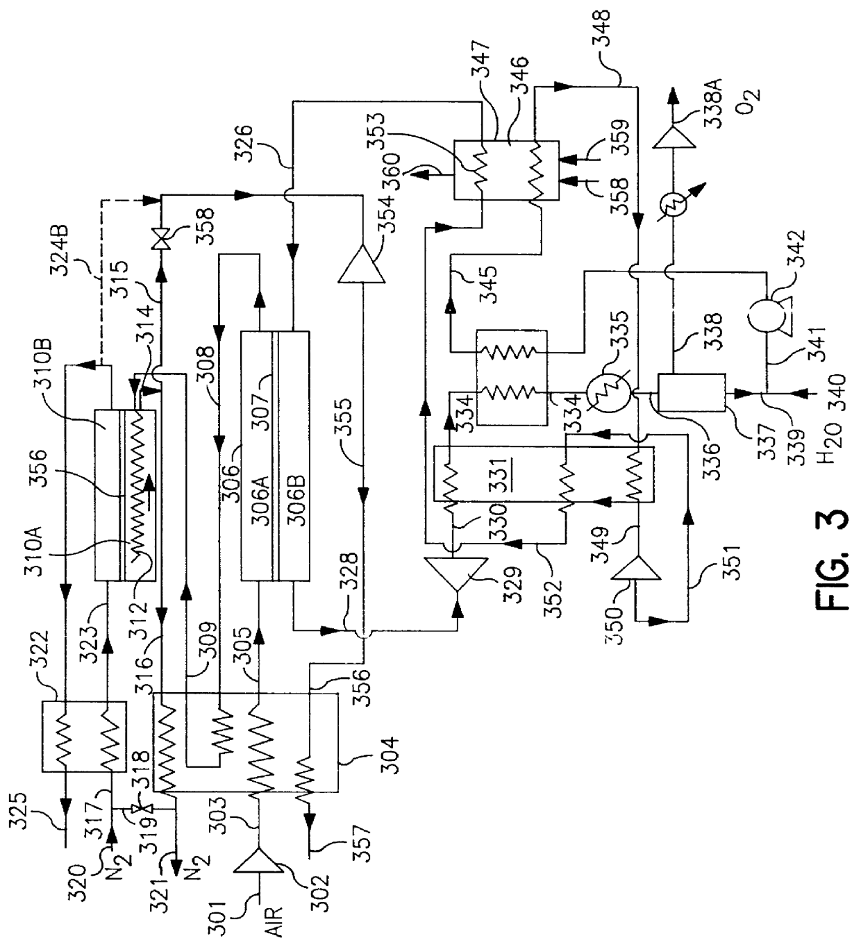
illustrates very attractive performance numbers for the embodiment of the invention as shown in FIG. 3. The use of a steam purge for the permeate side of the ion transport separator permits very high recovery of oxygen and therefore limits the amount of excess air that has to be processed by the system. Compared to Example 1, the amount of air is smaller by a factor of 3.1:1. The use of an ion transport reactor, which performs the deoxo function and at the same time generates the heat required for the air circuit, permits recovery of 90% of the nitrogen contained in the feed air at high product purity with a very simple cycle. Forty-one percent of the product nitrogen can be recovered at high pressure. The employment of a two-stage steam turbine cycle permits achieving very attractive energy utilization rates. The rates are significantly better than for the best case of Example 1 even though the former employs higher peak temperatures.
It should be noted that the cycles considered he...
example 3
Following is an example obtained by modeling a case employing the flow sheet of FIG. 4 and the reactor design of FIG. 5 with the assumptions listed below
Air Flow: 1130 MNCFH.
Air Compression to 115 psia in 3 stages with an adiabatic efficiency of 85%.
Air flow into reactor separator cooler:
225 MNCFH at 120.degree. F.
905 MNCFH at 400.degree. F.
Max oxygen transport membrane (OTM) operating temperature:
1760.degree. F.
Avg. OTM separator driving force:
log(PO.sub.cathode / PO.sub.anode)=0.3
Nitrogen flow leaving separator reactor cooler at 1300.degree. F.
Turbine Flow: 680 NCFH of N.sub.2 at 1300.degree. F.
Turbine efficiency: 85%.
Purge steam raised: 4.21 lbs / hr.
Fuel: Natural Gas with lower heating value of 900 BTU / NCFH
Fuel consumption: 18900 NCFH
Product flow:
200 MNCFH O.sub.2 contained (91.4% O.sub.2, 8.6% CO.sub.2) at 15 psia.
212 MNCFH N.sub.2 (O.sub.2 <10 ppm) at 100 psia.
Oxygen recovery: 84.3% of theoretical total.
KW for air compression--credit for product nitrogen compression: 10.03 / MNCFH ...
PUM
 Abstract
Description
Claims
Application Information