
Electrostatographic imaging member

a technology of electrographic imaging and member, applied in the direction of instruments, electrographic process equipment, optics, etc., can solve the problems of inability to remove the entire amount of debris inability to remove the entire amount during the cleaning process, and the flap upward movement presents an additional problem, so as to improve the thickness uniformity of the layer, improve the thickness of the backing layer, and improve the effect of anti-curl backing layer fabrication

Inactive Publication Date: 2001-10-16
XEROX CORP
View PDF12 Cites 62 Cited by
  • Summary
  • Abstract
  • Description
  • Claims
  • Application Information

AI Technical Summary

Benefits of technology

The advantageous effects achieved with the enhanced anti-curl backing layer fabrication utilizing the particle dispersion concept described above are achieved by using the dispersed ZONYL.RTM. PTFE particles in the material matrix of the outer exposed layers without producing any notable negative electrical impact on the final electrophotographic imaging member belt. Thus, the anti-curl backing layer formulation of this invention eliminates the formation of bubbles in the dried anti-curl backing layer. Elimination of the bubbles improves thickness uniformity of the layer and reduces mechanical wear rate. Further, elimination of the bubbles improves rear erase processes of a photoreceptor by achieving more uniform discharge. Also, open pits in the seam splashing are avoided and this result reduces undesirable dirt and increases cleaning blade life.
achieved with the enhanced anti-curl backing layer fabrication utilizing the particle dispersion concept described above are achieved by using the dispersed ZONYL.RTM. PTFE particles in the material matrix of the outer exposed layers without producing any notable negative electrical impact on the final electrophotographic imaging member belt. Thus, the anti-curl backing layer formulation of this invention eliminates the formation of bubbles in the dried anti-curl backing layer. Elimination of the bubbles improves thickness uniformity of the layer and reduces mechanical wear rate. Further, elimination of the bubbles improves rear erase processes of a photoreceptor by achieving more uniform discharge. Also, open pits in the seam splashing are avoided and this result reduces undesirable dirt and increases cleaning blade life.
The invention will further be illustrated in the following non-limiting examples, it being understood that these examples are intended to be illustrative only and that the invention is not intended to be limited to the materials, conditions, process parameters and the like recited herein. All proportions are by weight unless otherwise indicated.
CONTROL IMAGING MEMBER PREPARATION A flexible electrophotographic imaging member web stock was prepared by providing a 0.02 micrometer thick titanium layer coated on a flexible polyester substrate (MELINEX 442, available from I.C.I. Americas, Inc.) having a thickness of 3 mils (76.2 micrometers) and applying thereto, by a gravure coating process, a solution containing 10 grams gamma aminopropyltriethoxy silane, 10.1 grams distilled water, 3 grams acetic acid, 684.8 grams of 200 proof denatured alcohol and 200 grams heptane. This layer was then dried at 135.degree. C. in a forced air oven. The resulting blocking layer had an average dry thickness of 0.05 micrometer measured with an ellipsometer.
An adhesive interface layer was then extrusion coated by applying to the blocking layer a wet coating containing 5 percent by weight based on the total weight of the solution of polyester adhesive (MOR-ESTER 49,000, available from Morton International, Inc.) in a 70:30 volume ratio mixture of tetrahydrofuran / cyclohexanone. The resulting adhesive interface layer, after passing through an oven, had a dry thickness of 0.065 micrometers.
The adhesive interface layer was thereafter coated, by extrusion, with a photogenerating layer (CGL) containing 7.5 percent by volume trigonal Se, 25 percent by volume N,N'-diphenyl-N,N'-bis(3-methylphenyl)-1,1'-biphenyl-4,4'-diamine, and 67.5 percent by volume polyvinylcarbazole. This photogenerating layer was prepared by introducing 8 grams polyvinyl carbazole and 140 mL of a 1:1 volume ratio of a mixture of tetrahydrofuran and toluene into a 20 once amber bottle. To this solution was added 8 grams of trigonal selenium and 1,000 grams of 1 / 8 inch (3.2 millimeter) diameter stainless steel shot. This mixture was ball milled for 72 to 96 hours. Next, 50 grams of polyvinyl carbazole and 2.0 grams of N,N'-diphenyl-N,N'-bis(3-methylphenyl)-1,1'-biphenyl-4,4'-diamine dissolved in 75 mL of 1:1 volume ratio of tetrahydrofuran / toluene. This slurry was shaken on a shaker for 10 minutes. The resulting slurry was extrusion coated onto the adhesive interface layer to form a coating layer having a wet thickness of about 0.5 mil (12.7 micrometers). However, a strip about 10 millimeters wide along one edge of the substrate bearing the blocking layer and the adhesive layer was deliberately left uncoated by any of the photogenerating layer material to facilitate adequate electrical contact by a ground strip layer that was applied later. This photogenerating layer was dried at 135.degree. C. to form a dry photogenerating layer having a thickness of about 2.0 micrometers.

Problems solved by technology

The amount of the debris, however, is beyond the removal capacity of the cleaning instrument.
As a consequence, the cleaning instrument dislodges the highly concentrated level of debris but cannot remove the entire amount during the cleaning process.
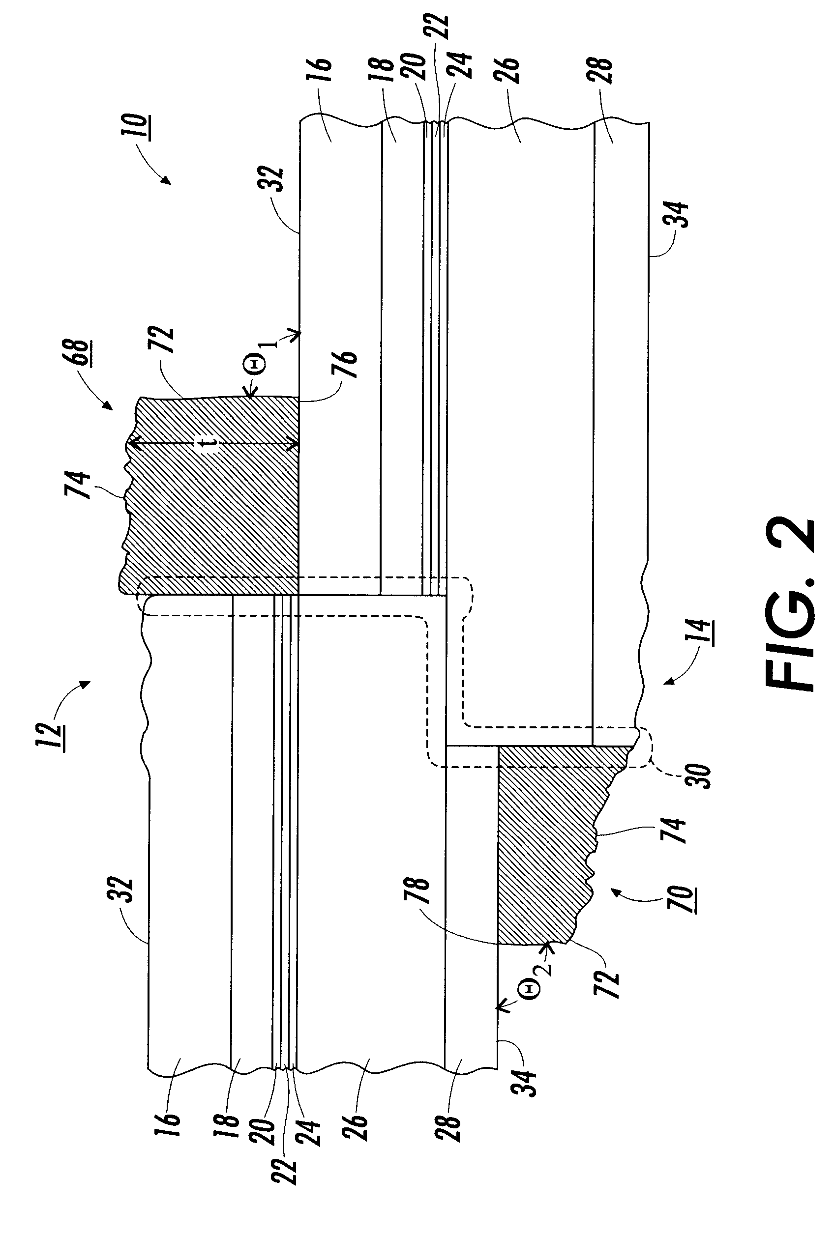
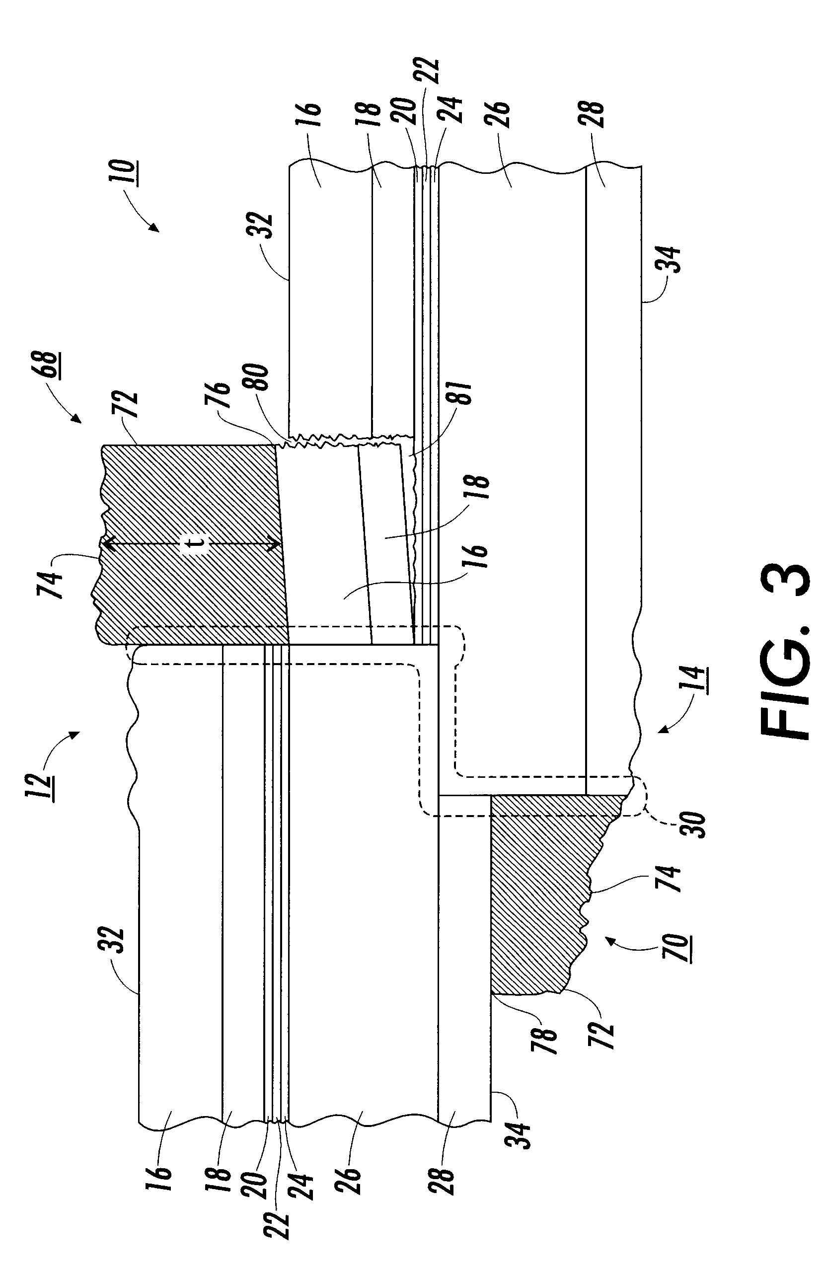
The upward movement of the flap presents an additional problem during the cleaning operation.
The flap becomes an obstacle in the path of the cleaning instrument as the instrument travels across the surface of the flexible imaging member belt 10.
As the cleaning instrument strikes the flap, great force is exerted on the cleaning instrument which can lead to instrument, for example, excessive wear and tearing of the cleaning blade.
Besides damaging the cleaning blade, the striking of the flap by the cleaning instrument causes unwanted vibration in the flexible imaging member belt 10.
This unwanted vibration adversely affects the copy / print quality produced by the flexible imaging member belt 10.
In addition, the rough and hard surface topology of the seam splashing is found to wear the cleaning blade and nick the contacting edge of the blade during electrophotographic imaging and cleaning processes, thereby reducing blade cleaning efficiency and shortening blade service life.
When fabricated into an imaging member belt and electrophotographically cycled in an imaging machine, these bubble defects prevent the anti-curl backing layer from making intimate surface contact against the belt support module drive-roller causing undesirable imaging member belt slippage due to insufficient generation of frictional force to effectively drive the belt.
These compounds may be added to polymeric materials which are incapable of supporting the injection of photogenerated holes from the generation material and incapable of allowing the transport of these holes therethrough.

Method used


Image

  • Electrostatographic imaging member
  • Electrostatographic imaging member
  • Electrostatographic imaging member

Examples


example iii

IMAGING MEMBER PREPARATION A flexible electrophotographic imaging member web stock was prepared according to Comparative Example II with the exception that the POLYMIST.RTM. dispersion in the anti-curl backing layer coating solution was replaced with ZONYL.RTM. MP1100, a commercial product of PTFE particles available from E.I. du Pont de Nemours & Company, to give a 10 weight percent dispersion of ZONYL.RTM. MP1100 particles in the resulting dry anti-curl backing layer.

ZONYL.RTM. MP1100 consists of small spherical shape PTFE particles prepared by a dispersion polymerization process. The small particle product obtained from this process possess a distinctive narrow particle size distribution of from about 0.19 micrometers to about 0.21 micrometers and an average primary particle size of about 0.20 micrometers. The ZONYL.RTM. MP1100 is also an electron-beam irradiated product. Since the initially formed PTFE particles are soft and are typically agglomerated into clustered particulates...

example iv

IMAGING MEMBER PREPARATION A flexible electrophotographic imaging member web stock was prepared according to Example III, with the exception that the resulting anti-curl backing layer contained ZONYL.RTM. MP1000 dispersion, an alternate PTFE product commercially available from du Pont. Since ZONYL.RTM. MP1000 is prepared by a similar process as the abovementioned ZONYL.RTM. MP1100, the MP1000 particles are also spherical in shape, have about the same particle size distribution, and have the same average primary particle size as the ZONYL.RTM. MP1000. However, the ZONYL.RTM. MP1000 product differs in that it received a lower dose of electron beam irradiation, which required a longer coating solution attrition time in order to break up particle agglomerates into primary particles and to effect homogeneous particle dispersion. The resulting dried anti-curl backing layer prepared with ZONYL.RTM. MP1000 on the imaging member web stock had no apparent bubble defects.

example v

FRICTIONAL WEAR AND RESISTANCE EVALUATION The electrophotographic imaging member web stocks of the above Control Example 1, Comparative Example II, and Examples III and IV were evaluated for interfacial contact friction interaction between the charge transport layer and the anti-curl backing layer to assess surface frictional forces that arise between these two contacting surfaces in a 6,000 foot wound up roll of an imaging member web stock. More specifically, the effect of the dispersed PTFE particles in the anti-curl backing layer on reduction of surface contact friction against the charge transport layer was determined. The coefficient of friction test was carried out by fastening a sample of an imaging member from each of the above mentioned Examples to a flat platform surface with the charge transport layer facing upwardly. Another identical imaging member sample from each Example was secured to the flat surface of the bottom of a horizontally sliding plate weighing 200 grams w...


PUM

PropertyMeasurementUnit
diameter particle sizeaaaaaaaaaa
diameter particle size distributionaaaaaaaaaa

Abstract

An electrostatographic imaging member including: a flexible supporting substrate; an imaging layer having an optional adjacent ground strip layer coated on one side of the substrate; and an anti-curl backing layer coated on the other side of the substrate which layer is comprised of a film forming polymer binder, an optional adhesion promoting polymer, and a dispersion of polytetrafluoroethylene particles which dispersion has particles with a narrow diameter particle size distribution of from about 0.19 micrometer to about 0.21 micrometer, and an average diameter particle size of about 0.20 micrometer. The optional ground strip layer can include the same dispersion of polytetrafluoroethylene particles as the anti-curl backing layer.

Description

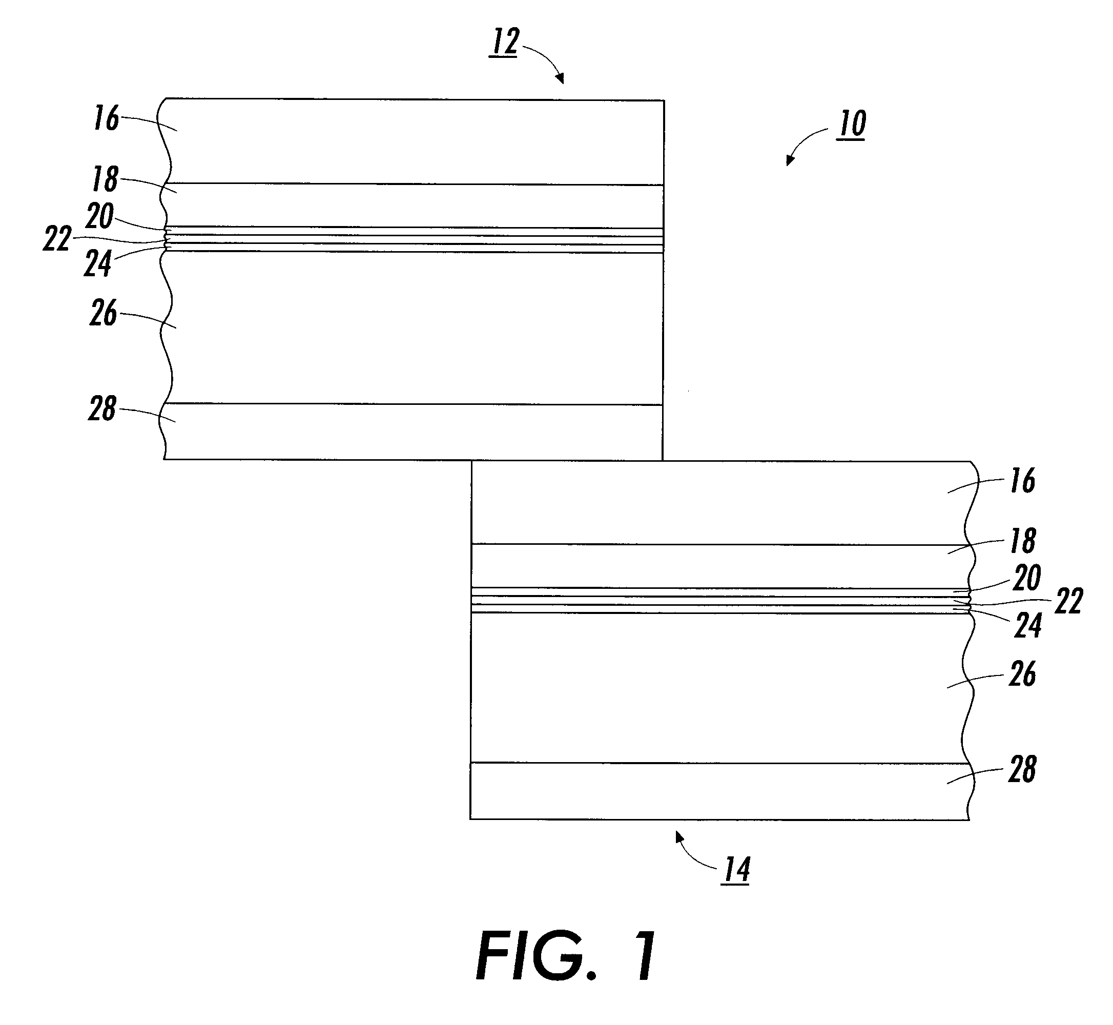
The present invention relates to flexible electrostatographic imaging belt members and, more specifically, to imaging belts having mechanically robust outer exposed layers that possess, for example, anti-curl backing layers or ground strip layers with enhanced wear resistance and optical transparency properties.Flexible electrophotographic imaging members are well known in the art. Typical electrostatographic flexible imaging members include, for example, photosensitive members, such as photoreceptors, commonly utilized in electrophotographic, such as xerographic processes and electroreceptors, and ionographic imaging members for electrographic imaging systems. The flexible electrostatographic imaging members may be seamless or seamed belts. Typical electrophotographic imaging member belts comprise an imaging layer which is a charge transport layer and a charge generating layer on one side of a supporting substrate layer and an anti-curl backing layer coated on the opposite side of ...

Claims


Application Information

Patent Timeline
Patent Type & Authority Patents(United States)
IPC IPC(8): G03G5/10
CPCG03G5/10
Inventor YU, ROBERT C. U.STREET, TERRY L.WAGNER, MORITZ P.
Owner XEROX CORP
Learn More