Automatic electrode positioning apparatus

a positioning apparatus and electrode technology, applied in the direction of electric programme control, program control, instruments, etc., can solve the problems of limited work, patch clamping technique, limited number of compounds that could be tested per day,

Inactive Publication Date: 2002-10-22
SOPHION BIOSCI
View PDF11 Cites 70 Cited by
  • Summary
  • Abstract
  • Description
  • Claims
  • Application Information

AI Technical Summary

Benefits of technology

In a preferred embodiment of the invention for automatical patch clamping of a cell, the apparatus may comprise a pipette comprising the electrode and having a pipette tip adapted to provide a high electrical resistance seal with the surface of a cell membrane. Then, the positioning means are adapted for holding and positioning the pipette at desired positions in relation to the chamber, and the controller is adapted for automatically controlling the positioning means in response to the received position in such a way that the pipette tip is positioned at the determined position of the selected cell and provides a high electrical resistance seal with the cell membrane of the selected cell whereby an electrical parameter of the cell membrane can be determined without intervention of a human operator.
The chamber member may be mounted on a mounting plate which can be moved in an x-y plane by two electromotors and the chamber member may be rotatable, e.g. by a third motor, about an axis perpendicular to the x-y plane so that the individual chambers can be positioned in their respective operating positions by rotation of the chamber member. The imaging system may further comprise an inverted microscope forming an assembly with the mounting plate. The position of the focus plane of the microscope may be adjustable thus, facilitating autofocussing prior to initiation of pipette and cell recognition.
It is a further object of the present invention to provide and adapt apparatus for automatic drug handling and application, and to utilize the apparatus in an electrophysiological system for screening of chemical substances or compounds to measure their effect on ion channel transfer, the novel system providing high throughput and low fluid volume requirements.
It is yet a further object of the present invention to reduce the needed amount of any chemical compound for testing as well as to increase the rate of screening, thereby providing the first electrophysiology test system suitable for commercial pharmaceutical company screening.

Problems solved by technology

However, they were limited in their work by the fact that the resistance of the seal between the glass of the pipette and the membrane (10-50 M.OMEGA.) was very small relative to the resistance of the channel (-10 G.OMEGA.).
However, a major obstacle of the patch clamp technique as a general method in pharmacological screening has been the limited number of compounds that could be tested per day (typically no more than 1 or 2).
Also, the very slow rate of solution change that can be accomplished around cells and patches may constitute a major obstacle.
A major limitation determining the throughput of the patch clamp technique is the nature of the feeding system, which leads the dissolved compound to perfused cells and patches.
However, a number of problems exist in the technique of the prior art.
First, the number of different compounds is limited by the number of bottles that may be connected to the application system at one time.
Second, the required volumes of the supporting liquid and the sample to be tested are critically high Third, the time needed to change the solute composition around cells and patches is long for usual patch clamp experiments.
Fourth, the introduction and application of compounds to be tested usually involves a significant degree of manual manipulation and interruption, thus jeopardizing the integrity of the cell / pipette connection.
However, the feeding systems which fill the U-tube are more inflexible and have lower capacity than those used for standard patch clamp.
This presently limits the use of these procedures in the medical industry.
It is a disadvantage of the known apparatus that various manual operations are required to utilize the apparatus.
1) Electrical noise. The introduction into a Faraday cage of any device which has to be powered by an alternating voltage will result in a source of 50 Hz or 60 Hz electromagnetic radiation. This may easily be picked up by the electrode in the patch pipette 62 (working as an antenna), thus disturbing the current signal. However, careful grounding of all metallic parts of the entire setup to a common high-quality ground will essentially solve this problem. Special care must be taken to ground and shield critical parts of the autosampler 20 to avoid excess electrical noise. When using other autosamplers, which possibly may be more difficult to ground effectively than the Gilson model utilized in the set-up shown in FIG. 1, it may become necessary to shield the autosampler in a separate Faraday cage.
2) Even weak mechanical vibrations may be transduced into low-frequency electrical noise appearing in the current signal.
Because of the extremely small size of the chamber, there is insufficient space for two electrodes to be Positioned in the microperfusion chamber 100.
Aspiration of excess fluid from the microperfusion chamber such as 72, 100, or 118 represents a special problem with small chambers, since a large fraction of the total chamber volume is aspirated per second.
Unstable liquid surfaces produce a variable background noise and may also confer an increased mechanical stress to the cell or patch, thereby limiting the recording period.

Method used


Image

  • Automatic electrode positioning apparatus
  • Automatic electrode positioning apparatus
  • Automatic electrode positioning apparatus

Examples


example 2

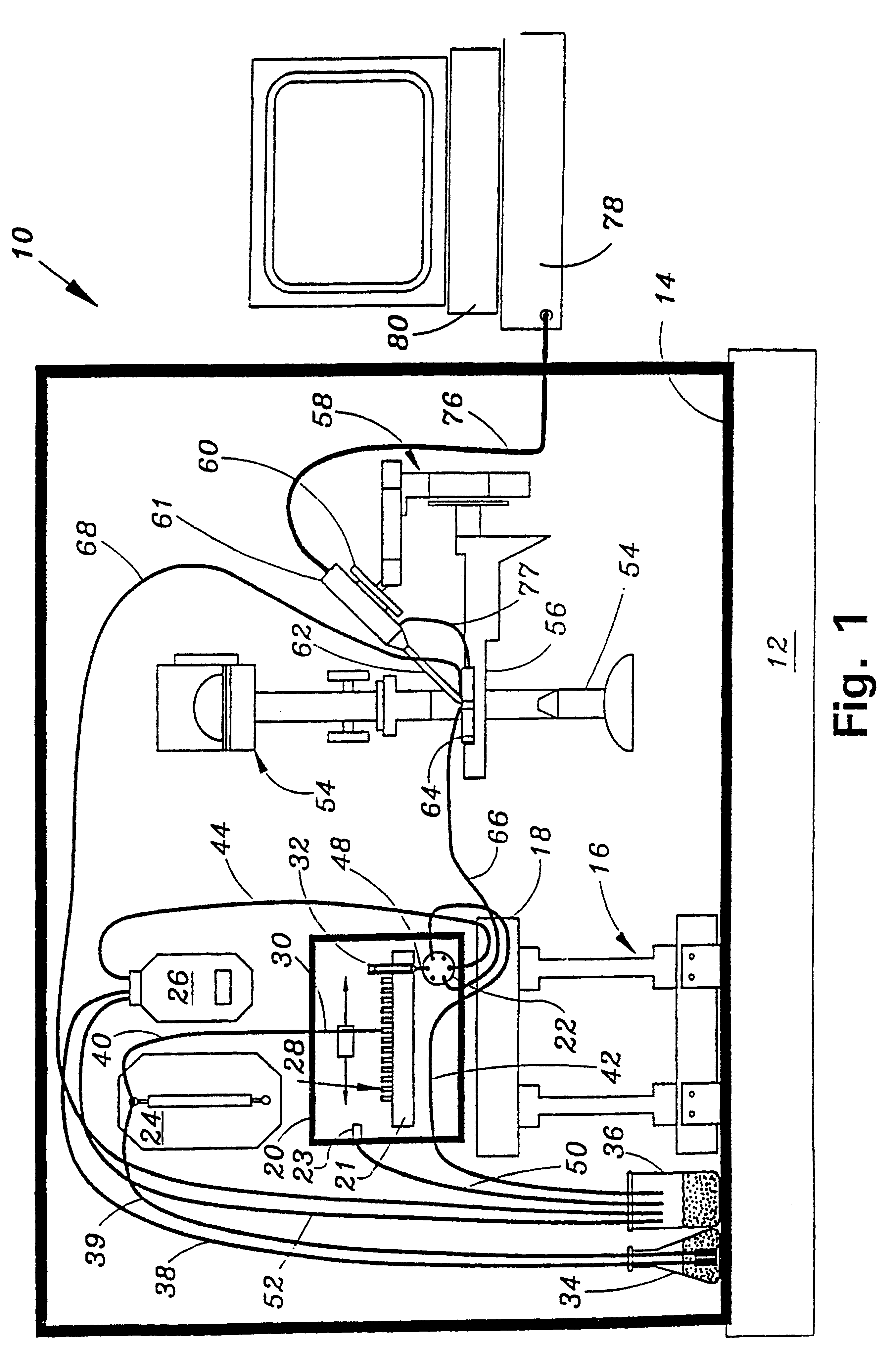
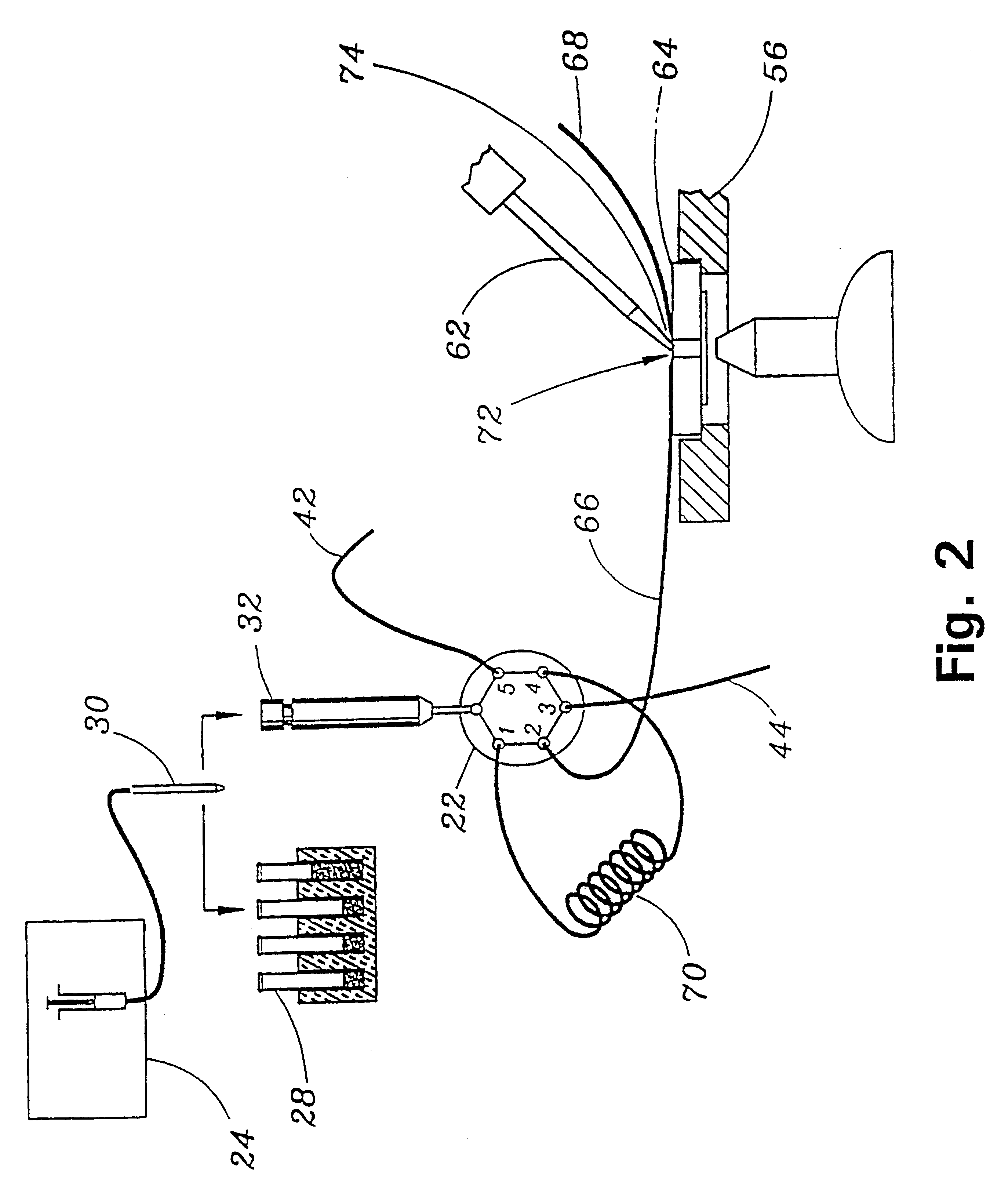
STOP-FLOW TECHNIQUE: The potassium current of a cultured human coronary smooth muscle cell was determined in an excised inside out patch by the stop- flow technique utilizing an apparatus as disclosed above and diagrammed in FIGS. 7-10, comprising an autosampler, syringe pump, and microperfusion chamber having a volume of 12 .mu.l.

The composition of the pipette and bath solutions was:

Pipette: KCl (140 mM), CaCl.sub.2 (1 mM), MgCl.sub.2 (1 mM), EGTA (1.3 mM), HEPES (10 mM).

Bath: KCl (140 ZuM), CaCl.sub.2 (1 mM), MgCl.sub.2 (1 mM), EGTA from 1.07 mM to 2.0 mM. The free Ca.sup.2+ concentration is determined by the concentration of EGTA. All test compounds were dissolved in bath solution with 0.3 pM free Ca2+.

The effects of 25 unknown compounds on calcium activated potassium channels were tested and reported in FIG. 12. In the experimental protocol, successive unknown compounds (open circles) were perfused (300 .mu.l) with intermittent washout with saline solution (filled circles). Each...


PUM

PropertyMeasurementUnit
resistanceaaaaaaaaaa
diameteraaaaaaaaaa

Abstract

The present invention relates to an automatic electrode position apparatus for connecting an electrode to a cell. The invention further provides methods for utilizing the apparatus of the invention. Apparatus and methods are described for studying electrical activities in cell membranes. These methods are especially useful in large scale screening programs in the pharmaceutical industry.

Description

The present invention relates to an apparatus for automatically connecting an electrode to a cell. Particularly, the present invention provides an apparatus for carrying out patch clamp techniques utilized to study electrical activities, such as ion transfer channels, in biological membranes. The present invention broadly refers to a novel electrophysiology drug handling and application set up for screening chemical substances or compounds, such as high throughput, requires a low volume of solution and sample to be tested. The invention further relates to methods for utilizing the apparatus of the invention, such as in large scale screening programs in the pharmaceutical industry.PRIOR ARTThe general idea of electrically isolating a patch of membrane using a micropipette and studying the ion channels in that patch under voltage-clamp conditions was outlined by Neher, Sakmann, and Steinback in "The Extracellular Patch Clamp, A Method For Resolving Currents Through Individual Open Cha...

Claims


Application Information

Patent Timeline
Patent Type & Authority Patents(United States)
IPC IPC(8): C12M1/34G01N33/483
CPCC12M1/3407G01N33/48728
Inventor OLESEN, SOREN-PETERCHRISTOPHERSEN, PALLEBECH, MORTEN
Owner SOPHION BIOSCI
Why Eureka
Try Eureka