In Situ concentration of an analyte

an analyte and concentration technology, applied in the field of in situ concentration of analyte, can solve the problems of sample loss, increased expense, and limited volume of standard volume pre-column inlet arrangement and existing large volume port technology

Inactive Publication Date: 2002-11-26
AGILENT TECH INC
View PDF17 Cites 21 Cited by
  • Summary
  • Abstract
  • Description
  • Claims
  • Application Information

AI Technical Summary

Benefits of technology

As the pressure on a liquid increases, the vapor pressure increases, therefore, the size and shape of the orifice from which the controlled delivery of the solvent will take place can be modified to maximize the surface area and its curvature. Higher curvature implies higher pressure and, therefore, higher vapor pressure by the Kelvin equation. A needle with a single opening will produce a droplet with relatively high surface area and curvature with a high rate of evaporation. An array of small orifices will greatly increase the area available for evaporation and, therefore, the rate of evaporation.
After the analyte 12 with excess solvent is delivered to the syringe needle tip 11, gas (carrier gas) flows over the syringe needle 10 to carry away evaporating solvent that exits the pre-column inlet 5'. The temperature of this gas is also controlled along with the pressure in the pre-column inlet 5'. It is also possible to valve shut the carrier or evaporating gas and apply a vacuum at the lower section of the pre-column inlet 5' near the gas outlet 15 which will allow the solvent to evaporate and exit. Controlling the needle temperature will prevent super cooling and freezing of the solvent at the syringe needle tip 11.
Controlling the temperature of the inlet chamber 34 will prevent re-condensation of solvent and promote condensation of any analyte 12 on the first wall 26 and second wall 28. Coating the first wall 26 and second wall 28 with phase (such as a column phase) will increase retentiveness and selectivity.
Delivery speed is controlled to optimize the retention of analyte 12 versus solvent. Because the variables of temperature, gas flow over the immerging solvent and needle or orifice design can be manipulated, there are several degrees of freedom available to optimize the concentration. Solvent can be evaporated to the point where the solution is nearly saturated--just prior to any precipitation or solid formation. At this point the remainder is rapidly dispensed and delivered into the inlet chamber 34 which can be ramped in temperature to aid delivery to the analytical column or pre-column inlet 5'. Similarly the needle temperature can be ramped simultaneously to enhance removal of analyte 12 and reduce carryover. It should also be mentioned that this method or process may include a compositing injection. In other words, the system can be designed to inject a number of samples or operate in a sequential manner with injections. This could provide for added concentration of analyte in the actual pre-column inlet chamber.
Referring to FIGS. 1, 2A and 2B, the injection means 5 may comprise the pre-column inlet 5' or similar type of device for receiving the analyte 12. A variety of inlet types exist and may be used with the present invention including and not limited to capillary direct inlets, split and splitless inlets, programmed temperature vaporizer inlets, cool on column inlets and other well known in the art. The programmed temperature vaporizer inlets (PTV) inlets work the best with the present invention, because of the flexibility of the instrument hardware. FIG. 2B shows a cross sectional view of a standard PTV inlet that may be used with the present invention. The pre-column inlet 5' comprises inlet port 7, pre-column housing 23, and gas inlet 13 for receiving a carrier gas and transporting the gas through a gas bore 16, across the longitudinal bore 21, until a gas outlet 15. The gas inlet 13 is connected to a gas supply line 14 that provides the carrier gas (shown in FIG. 1 only). A rubber gasket 18 is mounted near the inlet port 7 and has a centralized bore 19 (not labeled in FIG. 2B) designed for receiving the syringe needle 10. Rubber gasket 18 is secured to pre-column inlet 5' by lug nut 20. The centralized bore 19 is vertically aligned and disposed axially to the longitudinal bore 21, so that the syringe needle 10 may be inserted through the centralized bore 19 and the rubber gasket 18 into the longitudinal bore 21 (the centralized bore 19 is not labeled in any of the FIGS and passes directly through the rubber gasket 18).
Using a port or a zone, it is possible to evaporate or selectively remove solvent just prior to the injection of the analyte 12. As discussed above, the syringe 9' draws-up the analyte 12, moves to the pre-column inlet 5', inserts the syringe needle 10 through the rubber gasket 18, then slowly introduces the analyte 12. A gas (such as a carrier gas) flowing past the needle evaporates the solvent from the syringe needle tip 11. Analytes remain in the solvent at the syringe needle tip 11 rather than being carried away by evaporating the solvent. In addition, this technique has the advantage that the temperature of the gas can be controlled by the speed of the injection or delivery of the solvent to the tip. Coatings can be applied on the syringe needle tip 11, syringe 10, and / or walls 26 and 28 to assist in the recovery of the analyte 12 that tends to escape or evaporate with the solvent. Controlling the temperature of the injection port will allow the collection of analytes over solvent.

Problems solved by technology

These steps are time-consuming, subject to loss, usually require specialized equipment and technical expertise all of which lead to increased expense.
This approach suffers from a limitation on volume that can be contained inside the pre-column inlet and, therefore, any increases in volume must be obtained by consecutive injections and evaporation cycles that can result in sample losses.
However, these large-volume pre-column inlets have been considered attractive relative to the standard pre-column inlet such as split / splitless or on-column that only allow less than 4-.mu.l injections and provide no capability for in-situ concentration.
Both the standard volume pre-column inlet arrangements and the existing large volume port technologies are limited in the volume that can be concentrated by the fact that liquid injections vaporize inside the port and mechanical arrangements (namely, the liquid or vapor volume that can be contained) place an upper bound on the concentration factors that can be achieved.
For instance, some products may need to be concentrated, because they are expensive to derivatize, difficult to extract or synthesize.
However, low concentrations of product can be a problem for a researcher, because they may challenge the limits of instrument sensitivities or increase the possibility of inaccurate abundance measurements.
In addition, the transfer of these analytes from instrument to instrument or from instrument to storage container can result in significant additional loss of product.
However, these devices often require access to a centrifuge or micro-centrifuge for spinning the analytes and are effective only when concentrating small volumes.
However, most of these methods and instruments suffer from the limitation of possible loss of analyte.
In addition, since the concentration of analyte is performed separately, these methods can be time intensive and laborious.
Present chromatographic technology, however, requires additional hardware, components or complex instrumentation design to appropriately concentrate analytes.
A problem with this type of device is that the analyte is too dilute or contains a volatile solvent that significantly lowers the amount of sample concentration.
However, these systems have only been used to concentrate analytes after they have been ejected from the syringe needle into the pre-column inlet.
These techniques are not designed for concentrating the analyte at the pre-column stage.
A disadvantage of this is that lower amounts of analyte are loaded onto the column and by the time the separated components reach the final mass analyzer, a low signal to noise ratio is obtained.
This negatively affects the overall results.

Method used


Image

  • In Situ concentration of an analyte
  • In Situ concentration of an analyte
  • In Situ concentration of an analyte

Examples


Embodiment Construction

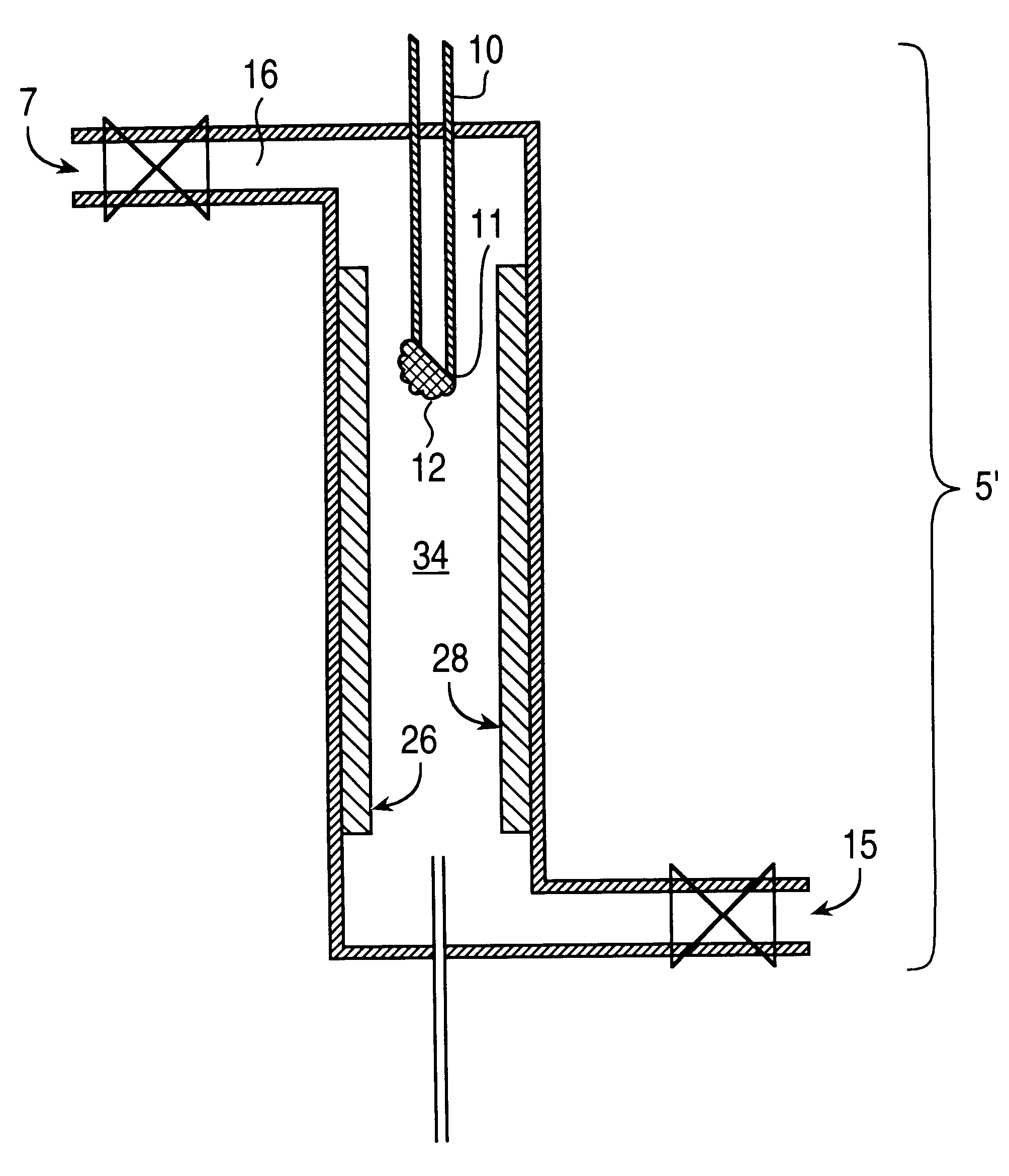
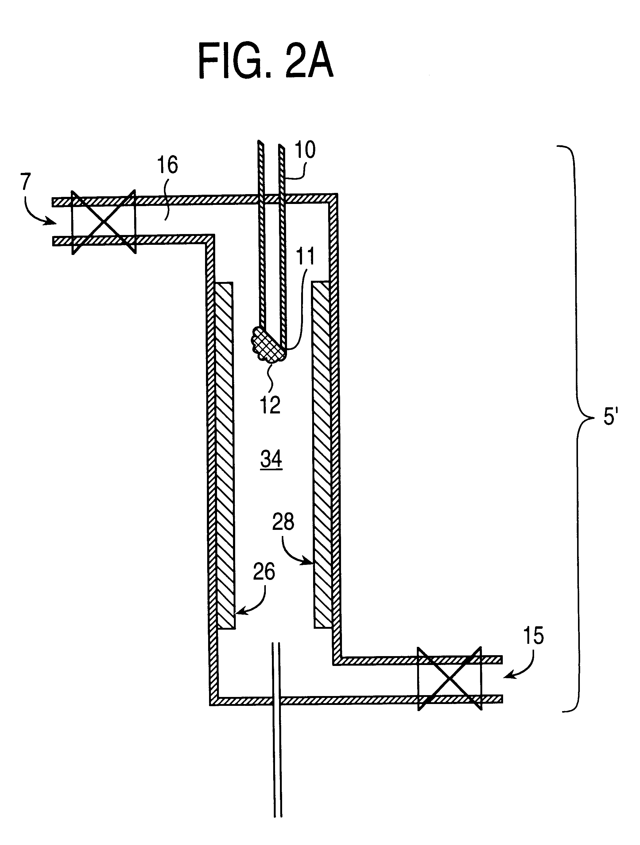
As a specific example, typical analyte concentration factors are around 1000-fold before injecting 1 or 2 micro-liters of solution out of a total volume of 1-ml; i.e., 1000-ml of extraction solvent is condensed to 1-ml. If the injection volume is scaled up to 100 .mu.l, then to maintain the same effective amount of analyte injected, only a 10-fold concentration factor need be generated on the bench; i.e., 10-ml of extraction solvent is condensed to 1-ml. The extract is concentrated about 20 or 1000 fold. Solvent can be readily removed from analyte according to the results of various tests that may be conducted with the solvent, rate of heating / gas flow, amount of sample dispensed onto the syringe needle tip, miscibility and volatility of the solvents, shape of the syringe needle tip as well as materials and compositions. Each of these factors could effect the overall final concentration of the analyte that remains on the syringe needle tip. In addition, the rate of gas flow and samp...


PUM

PropertyMeasurementUnit
boiling pointaaaaaaaaaa
concentrationaaaaaaaaaa
timeaaaaaaaaaa

Abstract

An apparatus and method for selectively concentrating an analyte on an apparatus by evaporating solvent from the analyte. Concentration is performed by heating or by flowing a gas stream over the analyte to evaporate solvent from the analyte. The invention also provides a method to be used in conjunction with the apparatus.

Description

The present invention relates to the field of chromatography and more particularly toward an apparatus and method for concentrating an analyte prior to an analytical detector such as a mass spectrometer.Although analytical instrumentation is becoming increasingly sensitive and analyte detection continues to improve, many chemical analytes require concentration prior to chemical analysis. Typically this is done using bench-top chemical processes specifically developed or tailored to the analytical problem. Representative of these approaches are solvent condensation or evaporation techniques that eliminate the solvent while retaining the analyte (or analytes--in all cases analyte could just as well as be analytes) by exploiting differences in physical properties such as volatility. Nitrogen or inert gas "blown-downs", rotary evaporation, Kuderna-Danish condensers, distillation (steam, etc.), tube heaters, vacuum evaporation, (freeze drying), and related techniques are typical of appro...

Claims


Application Information

Patent Timeline
Patent Type & Authority Patents(United States)
IPC IPC(8): G01N30/00G01N30/12G01N1/40G01N30/18
CPCG01N1/40G01N30/12G01N30/18G01N2001/4027G01N2030/127
Inventor PREST, HARRY F.
Owner AGILENT TECH INC
Why Eureka
Try Eureka