Broad spectrum reflective coating for an electric lamp

a reflective coating and broad spectrum technology, applied in the direction of optical elements, lighting and heating apparatus, instruments, etc., can solve the problems of short-lived oxidation-susceptible coatings, reducing their effectiveness, and economically impractical coatings utilizing expensive elements

Inactive Publication Date: 2003-03-18
GENERAL ELECTRIC CO
View PDF9 Cites 48 Cited by
  • Summary
  • Abstract
  • Description
  • Claims
  • Application Information

AI Technical Summary

Benefits of technology

In a portion of the infrared spectrum of from about 800 nm to about 1,200 nm, one embodiment of the coating 22 includes a spectral high reflectance of at least 80% at a normal angle of incidence. Other embodiments include a spectral high reflectance of at least 50% in the portion of the infrared spectrum of from about 800 nm to about 1,500 nm. The spectral high reflectance of at least 90% of the wavelengths in this range is at least 60%. At least 30% of the wavelengths in the 800 nm to 1,500 nm range are reflected at a level of 80% and at least 10% of the wavelengths in this range are reflected at a level of at lea

Problems solved by technology

These coatings reflected both visible light and infrared radiation, but had significant disadvantages.
The coatings utilizing expensive elements were economically impractical for many uses, while the oxidation-susceptible coatings were short-lived due to a relatively rapid decrease in their effectiveness because of oxidation.
These coatings of the prior art have not exhibited a high level of reflectance of substantially all wavelengths in the both the visible spectrum and a portion of the infrared spectrum.
Tran

Method used


Image

  • Broad spectrum reflective coating for an electric lamp
  • Broad spectrum reflective coating for an electric lamp
  • Broad spectrum reflective coating for an electric lamp

Examples


example 1

Prior Art Coating

FIG. 4 is a plot illustrating the spectrum of wavelengths reflected versus the percentage of each wavelength reflected by a typical dichroic coating of the prior art. Twenty-six (26) layers comprise the structure of the coating. The physical thickness of each layer in Angstroms (.ANG.) is shown in Table 1 below, where L is a low refractive index material and H is a high refractive index material. Layer 1 is the layer closest to the substrate.

[t2]

For the majority of the visible portion of the spectrum, commencing with a lower end of high reflectance 25, at a wavelength of about 400 nm, and ending at a higher end of high reflectance 26, at a wavelength of just over 800 nm, a coating of the prior art exhibits a spectral high reflectance in the approximate range of 90% or higher. Thus, the spectral high reflectance of a typical prior art coating is about 90% from approximately 400 nm to just over 800 nm.

The portion of the electromagnetic spectrum that includes infrared ...

example 2

Exemplary Embodiment of the Present Invention

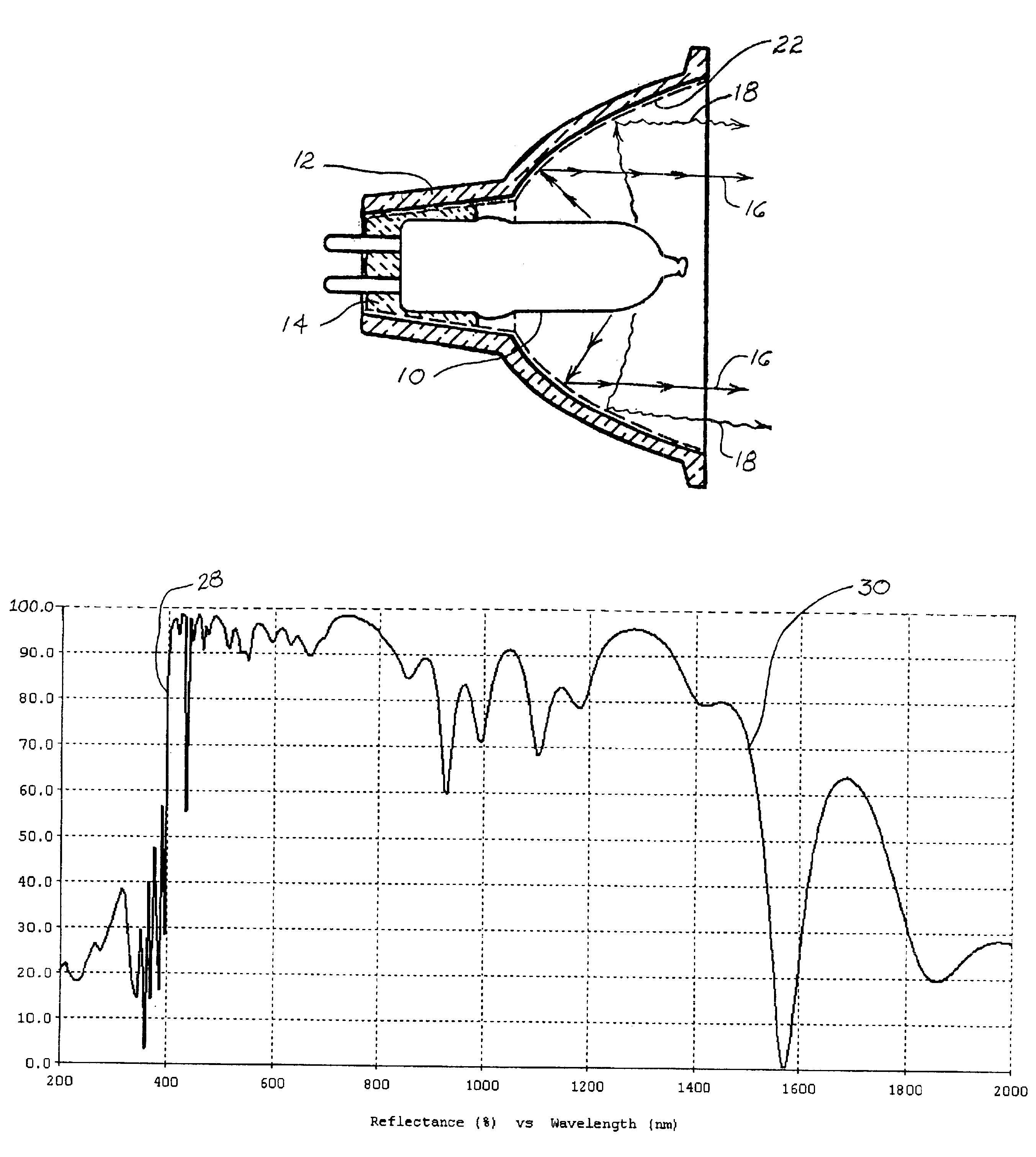
FIG. 5 is a plot showing the spectrum of wavelengths reflected versus the percentage of each wavelength reflected by an exemplary embodiment at a normal angle of incidence. The materials used for this embodiment are alternating layers of titanium dioxide (TiO.sub.2) and silicon dioxide (SiO.sub.2). The titanium dioxide is the high refractive index material and the silicon dioxide is the low refractive index material. The coating is optimized at a target angle of incidence of 0.degree. and includes wavelengths extending from 400 nm to 1,500 nm, with wavelengths from 400 nm to 800 nm receiving a higher weighting than those over 800 nm. The substrate material is glass.

Thirty-nine (39) alternating layers of TiO.sub.2 and SiO.sub.2 comprise the dichroic structure of the coating. The physical thickness in Angstroms (.ANG.) of each layer is shown in Table 2 below. Layer 1 is the layer closest to the glass substrate.

[t1]

The dichroic structure of ...

example 3

A Second Exemplary Embodiment of the Present Invention

FIG. 7 is a plot showing the spectrum of wavelengths reflected versus the percentage of each wavelength reflected by another exemplary embodiment at a normal angle of incidence. The materials used for this embodiment are alternating layers of titanium dioxide (TiO.sub.2) and silicon dioxide (SiO.sub.2). The titanium dioxide is the high refractive index material and the silicon dioxide is the low refractive index material. The coating is optimized at a target angle of incidence of 0.degree. and includes wavelengths extending from 400 nm to 1,200 nm, with wavelengths from 400 nm to 800 nm receiving a higher weighting than those over 800 nm. The substrate material is glass.

Twenty-six (26) alternating layers of TiO.sub.2 and SiO.sub.2 comprise the dichroic structure of the coating. The physical thickness of each layer in Angstroms (.ANG.) is shown in Table 3 below. Layer 1 is the layer closest to the glass substrate.

[t4]

The dichroic ...


PUM

PropertyMeasurementUnit
Fractionaaaaaaaaaa
Fractionaaaaaaaaaa
Nanoscale particle sizeaaaaaaaaaa

Abstract

An interference coating (22) for reflecting both visible light and a portion of the region of the infrared spectrum is disclosed. The coating includes a dichroic structure of a plurality of layers of a material having a low index of refraction and a plurality of layers of a material having a high index of refraction. The coating has an average spectral high reflectance of at least 80% for wavelengths in the visible light section of the electromagnetic spectrum and of at least 50% for wavelengths in a portion of the infrared section of the electromagnetic spectrum at least 150 nm wide.

Description

BACKGROUND OF INVENTIONCoatings for use on reflectors of electric lamp assemblies are well known in the art. Early coatings included metallic elements that were expensive, such as gold or platinum, or elements that were or susceptible to oxidation, such as silver or aluminum. These coatings reflected both visible light and infrared radiation, but had significant disadvantages. The coatings utilizing expensive elements were economically impractical for many uses, while the oxidation-susceptible coatings were short-lived due to a relatively rapid decrease in their effectiveness because of oxidation.Dichroic coatings were developed, in part, as inexpensive and oxidation-resistant alternatives to metallic coatings. Dichroic coatings include layers of oxides of materials that typically have low absorption of radiation in the visible light and infrared portions of the electromagnetic spectrum and that are thermally and mechanically stable. Examples include oxides of titanium, silicon, tan...

Claims


Application Information

Patent Timeline
IPC IPC(8): G02B5/26G02B5/28H01J61/40H01J5/02H01J5/16H01J61/38H01K1/28H01K1/32F21V7/22F21V9/08
CPCF21V7/22G02B5/281F21V9/08F21V7/24F21V7/28
Inventor SPIRO, CLIFFORD LAWRENCEISRAEL, RAJASINGHBROWN, PETER
Owner GENERAL ELECTRIC CO
Why Eureka
Try Eureka