Process and apparatus for cleaning and/or coating metal surfaces using electro-plasma technology

Inactive Publication Date: 2003-07-01
CAP TECH LLC 50 DANILA VITALEVICH RYABKOV 50 +1
View PDF7 Cites 36 Cited by
  • Summary
  • Abstract
  • Description
  • Claims
  • Application Information

AI Technical Summary

Problems solved by technology

However, the energy consumption of this process is high (10 to 30 kWh/m.sup.2) as compared to the energy consumption for acid pickling (0.4 to 1.8 kWh/m.sup.2).
Whilst low voltage electrolytic cleanin

Method used


Image

  • Process and apparatus for cleaning and/or coating metal surfaces using electro-plasma technology
  • Process and apparatus for cleaning and/or coating metal surfaces using electro-plasma technology
  • Process and apparatus for cleaning and/or coating metal surfaces using electro-plasma technology

Examples


example 1

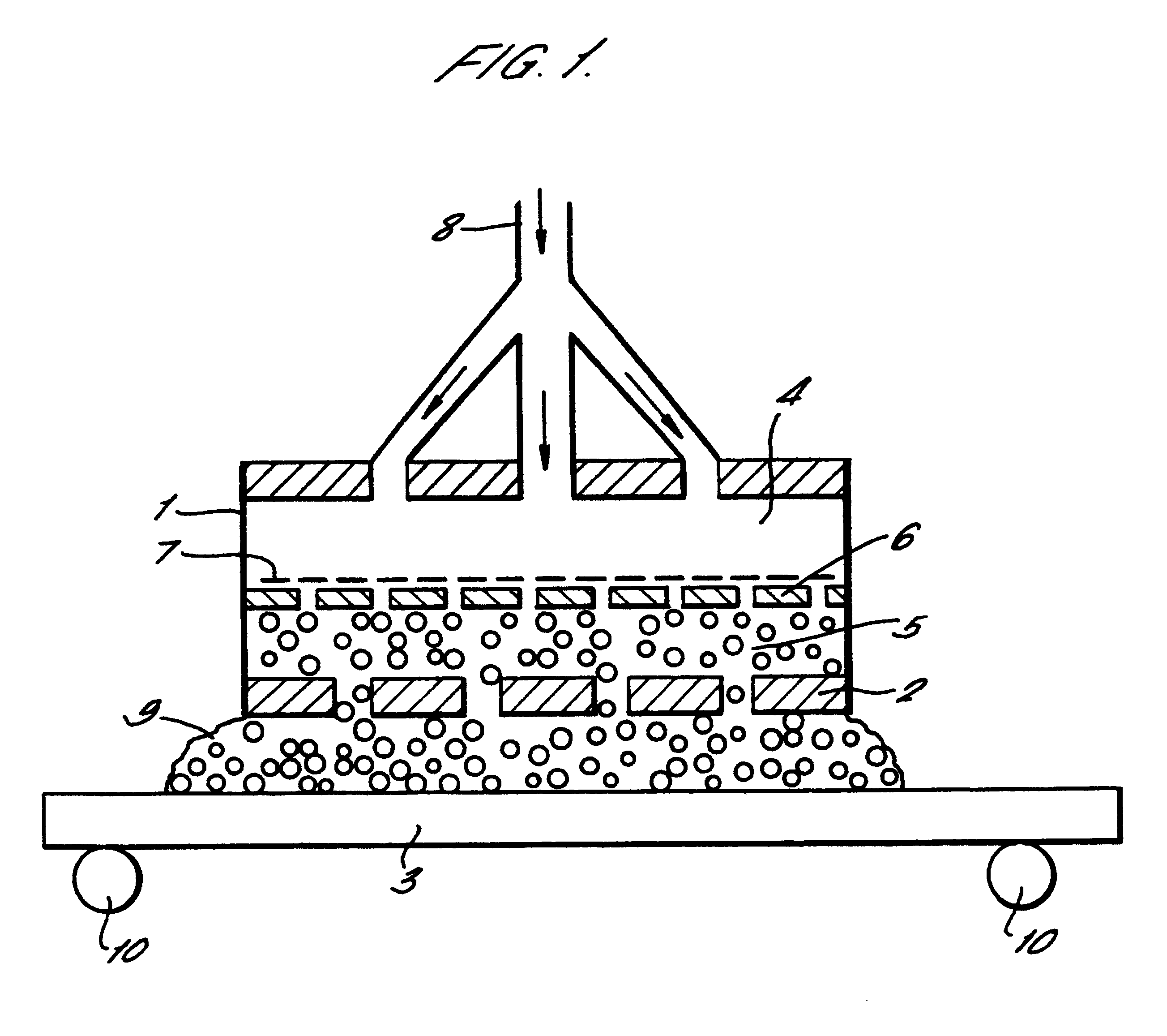
A continuous strip of low-carbon steel covered on both sides with a layer of black mill-scale was passed vertically through the closed apparatus shown in FIG. 2 at a steady speed of about 1 cm / sec. The width of the strip was 10 cm and the working area of each anode was 10 cm.times.10 cm.

An electrolyte consisting of a 10% solution of sodium bicarbonate in water was pre-heated to 90.degree. C. and caused to flow through holes in the anode plates situated on either side of the strip into a working gap (anode-to-workpiece distance) of 10 mm.

Initially the electrolyte pooled at the bottom of the chamber, being partially retained by the rubber seals. A DC voltage was applied to the anode (the strip being earthed) and automatically limited to about 10V on account of the high current flow of above 40 amps.

The flow-rate of the electrolyte was gradually decreased until resistive heating of the pooled liquid electrolyte at the bottom of the chamber caused it to boil and foam, filling the workin...

example 2

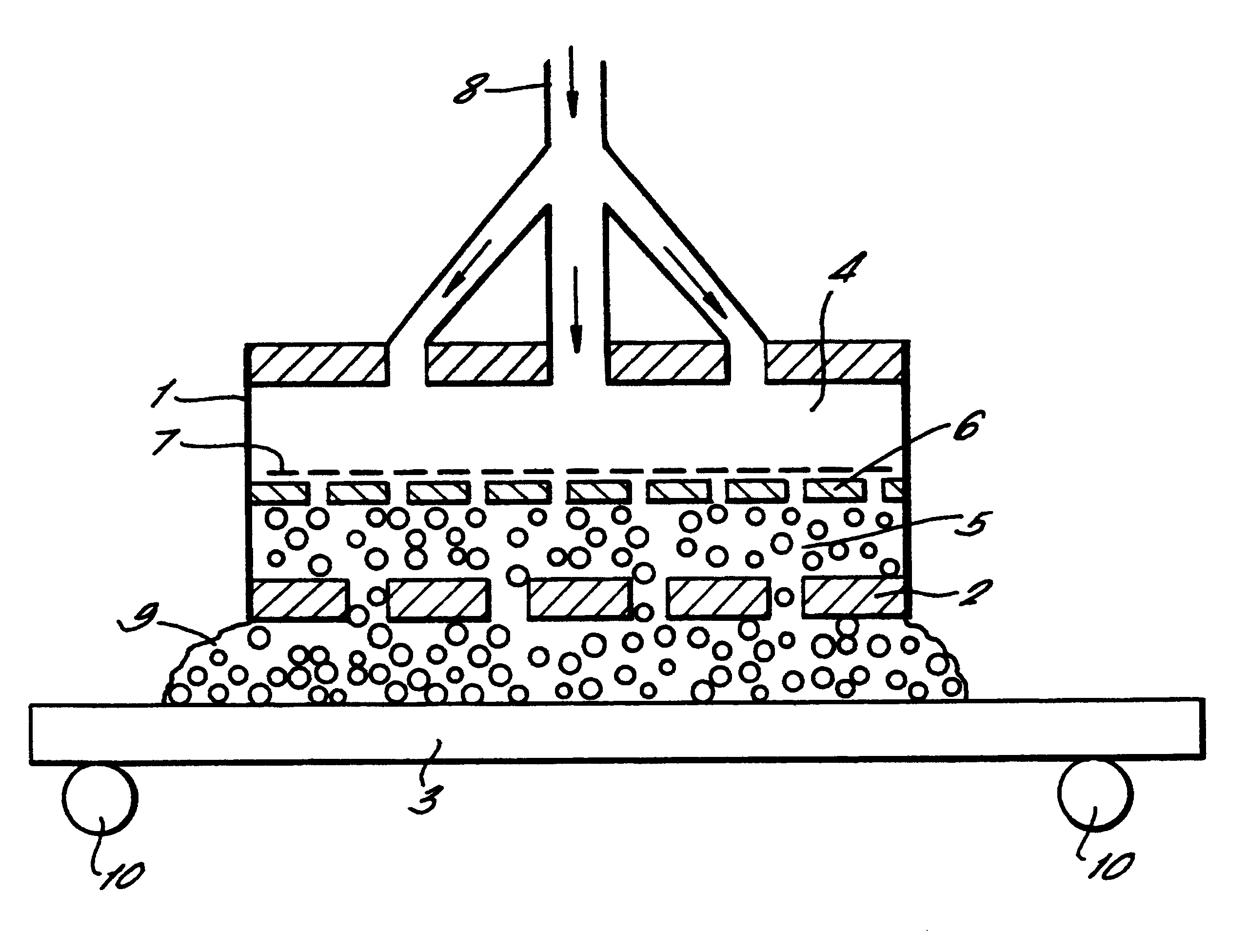
A continuous low-carbon steel strip as in Example 1 was passed horizontally through an apparatus as shown in FIG. 1 at a speed of around 1 cm / sec. An electrolyte as described in example 1 was caused to flow through holes in the anode plate into the working gap above the strip, which was set at 10 mm. A DC voltage of 200V is applied to the anode. Initially the electrolyte consisted of liquid streams, and a stable plasma was established on the surface of the strip by gradually reducing the flow-rate of the electrolyte.

The internal heater in the anode assembly was turned on, raising the temperature of the electrolyte and causing it to fill the working gap substantially in the form of a foam. While the process was running, the working gap was increased to 20 mm without destroying the plasma or disrupting the cleaning process.

Without a foaming electrolyte (that is, using only liquid electrolyte streams) such an increase in the working gap causes the plasma to be quenched. Thus larger wor...

example 3

A stationary copper sheet was cleaned of oxide in an apparatus as shown in FIG. 2. The process was essentially as described in Example 1 except that the electrolyte consisted of a saturated solution of sodium chloride heated to 90.degree. C. In this case, however, the electrolyte exhaust tube was restricted by a clamp in order to generate a slightly elevated pressure in the enclosed working chamber, estimated at 112 kPa.

The copper sheet was cleaned and the resulting surface was smoother than that produced using a liquid electrolyte, at atmospheric pressure and without foaming, in an apparatus such as that shown in FIG. 1.


PUM

PropertyMeasurementUnit
Electric potential / voltageaaaaaaaaaa
Temperatureaaaaaaaaaa
Pressureaaaaaaaaaa

Abstract

A process for cleaning an electrically conducting surface (3) by arranging for the surface to form the cathode of an electrolytic cell in which the anode (1) is maintained at a DC voltage in excess of 30V and an electrical arc discharge (electro-plasma) is established at the surface of the workpiece by suitable adjustment of the operating parameters, characterized in that the working gap between the anode and the cathode is filled with an electrically conductive medium consisting of a foam (9) comprising a gas/vapor phase and a liquid phase. The process can be adapted for simultaneously coating the metal surface by including ions of the species required to form the coating in the electrically conductive medium. Apparatus for carrying out the process is also disclosed and, in particular, an anode assembly (1) which comprises a perforated anode plate (2) which is in communication with a chamber (4) adapted to receive a flow of a liquid electrolyte, means to supply the liquid electrolyte to the chamber, and means (7) to convert the liquid electrolyte received in the chamber into a foam.

Description

The present invention relates to an improved process and apparatus for cleaning and / or coating metal surfaces using electro-plasma technology.Metals, notably, steel in its many forms, usually need to be cleaned and / or protected from corrosion before being put to their final use. As produced, steel normally has a film of mill-scale (black oxide) on its surface which is not uniformly adherent and renders the underlying material liable to galvanic corrosion. The mill-scale must therefore be removed before the steel can be painted, coated or metallised (e.g. with zinc). The metal may also have other forms of contamination (known in the industry as "soil") on its surface including rust, oil or grease, pigmented drawing compounds, chips and cutting fluid, and polishing and buffing compounds. All of these must normally be removed. Even stainless steel may have an excess of mixed oxide on its surface which needs removal before subsequent use.Traditional methods of cleaning metal surfaces in...

Claims


Application Information

Patent Timeline
IPC IPC(8): C25F1/00C23C26/00C23G5/00C25D7/06C25D5/00C25F7/00
CPCC23C26/00C25D5/00C25F1/00C25D5/06C25D5/003C25D5/623
Inventor RYABKOV, DANILA VITALIEVICH
Owner CAP TECH LLC 50 DANILA VITALEVICH RYABKOV 50
Why Eureka
Try Eureka