Eureka AIR delivers breakthrough ideas for toughest innovation challenges, trusted by R&D personnel around the world.

Ionization chamber for reactive samples

Inactive Publication Date: 2003-08-19
AGILENT TECH INC
View PDF15 Cites 18 Cited by
  • Summary
  • Abstract
  • Description
  • Claims
  • Application Information

AI Technical Summary

Benefits of technology

It is another object of the invention to provide such an ionization chamber, particularly an EI chamber, for improved performance in a mass spectrometer.
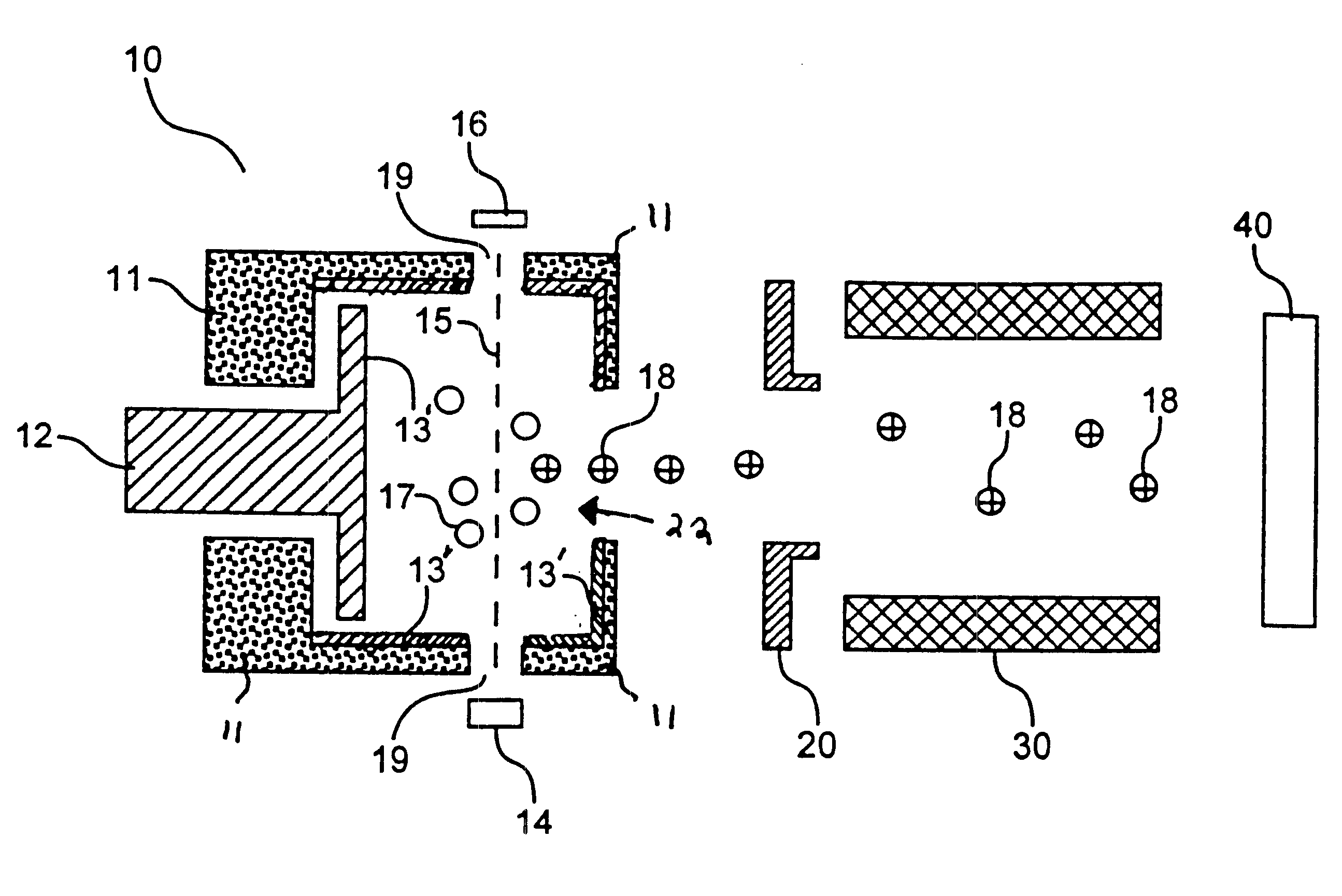
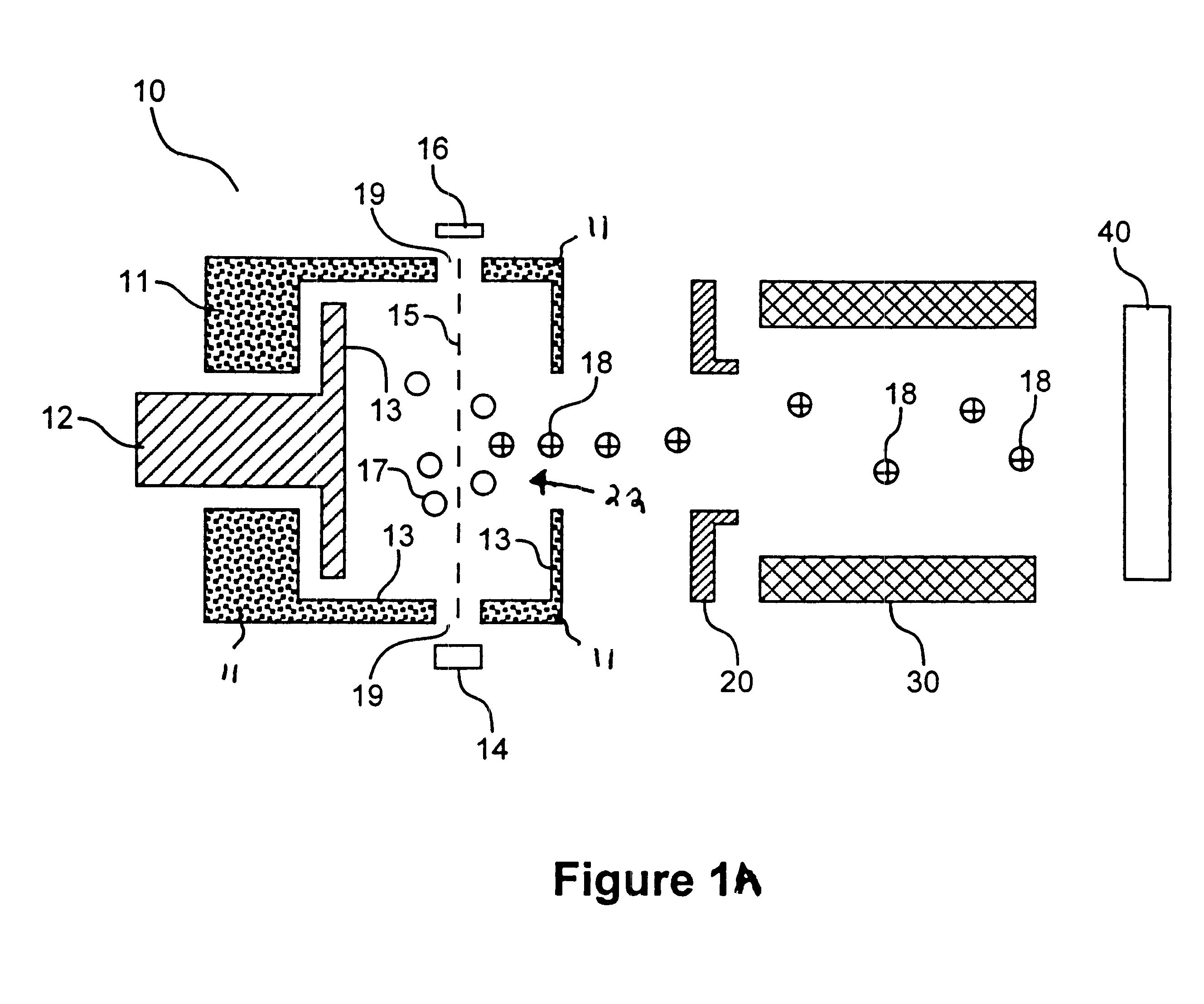
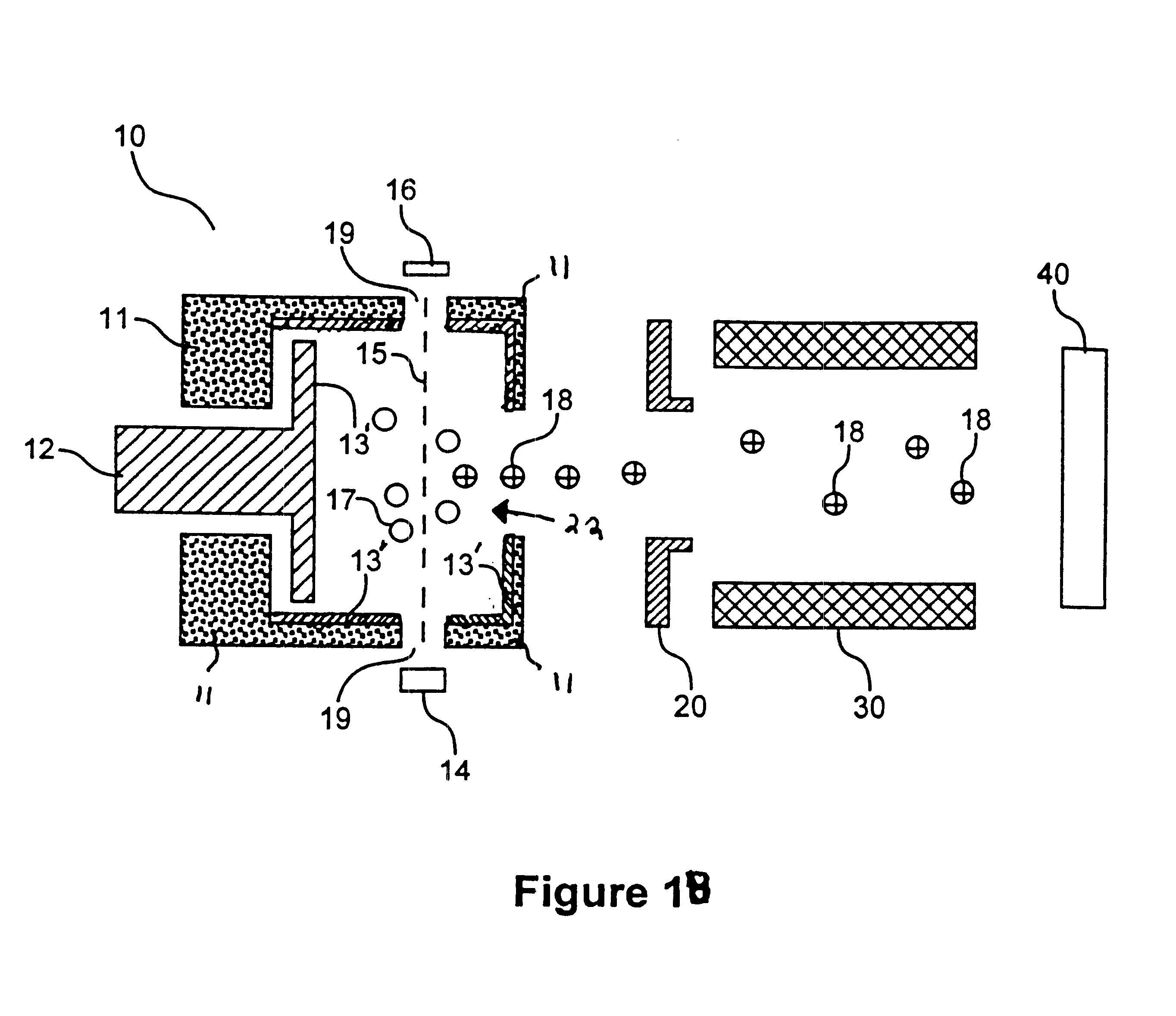
Alternatively, a preferred inner surface for an ionization chamber is a conductive disulfide compound. The disulfide compound may exhibit a layered microstructure. Examples of conductive disulfide layered compounds include, but are not limited to, tungsten disulfide, molybdenum disulfide, iron disulfide, copper disulfide, and titanium disulfide. These layered compounds are generally chemically inert at elevated temperatures. In particular, tungsten disulfide has unexpectedly been found to exhibit excellent inert properties in mass spectrometry applications. When surfaces of an ionization chamber are coated with a layered material such as tungsten disulfide, the layered compound provides lubrication that in turn facilitates assembly of components that formn the ionization chamber or that are disposed within the ionization chamber. Surprisingly, these materials have also been found to be inert with respect to certain known reactive analytes and to be hard and mechanically robust.
As another alternative, the surface coating material can be applied as a powder. One method of powder application involves providing the conductive compound in powdered form and employing high pressure to spray the powder entrained in a fluid at high velocity such that the powder mechanically adheres to the surface. Another method involves suspending the powder in a solvent to form a paint, applying the paint onto the surface, and evaporating the solvent. The solvent can be a relatively inert carrier or one that facilitates chemical bonding between the powder particles or between the powder and the surface. In addition, heat can be applied to evaporate the solvent or to promote chemical bonding. Typically, no organic binder is used because organic materials generally outgas at sufficiently high vapor pressure to produce a gas phase that is ionized along with the sample, producing a high background in the mass spectrum. However, the film of the present invention does not necessarily preclude inclusion of a small amount of an organic binder if overall outgassing is sufficiently low. Typically, powder application is well suited for disulfides such as molybdenum disulfide, tungsten disulfide, chromium disulfide, etc. However, one drawback to this method is that the resulting coating does not withstand abrasive cleaning as well and may have to be reapplied over time.

Problems solved by technology

The interaction of the sample with these surfaces may create an undesired effect.
For example, if a portion of the sample adheres to the chamber surface, the portion cannot be effectively ionized and directed to the detector.
As a result, the sensitivity of the apparatus for analysis of that analyte may suffer.
The results are undesirable: chromatographic peak tailing, loss of sensitivity, nonlinearity, erratic performance and the like.
Contamination is unacceptable in such analyses, so residual analytes or analyte reaction products from previous tests would not be tolerable.
However, the same undesired interactions of the sample with the source chamber surfaces may occur in a CI source as in an EI source as mentioned above.
However, mass spectrometers using such ionization chambers have been found to give variable results and still exhibit degradation of the analyte over time.
Such surfaces suffer from a variety of drawbacks such as susceptibility to scratching when the metal coating is soft or assembly / diassembly difficulties when the coating has a high coefficient of friction.
Because these surface coatings exhibit high electrical resistivity, however, electrical charge can undesirably accumulate on these coatings if the coatings are too thick.
Unfortunately, the materials used for such treatments have a sufficiently high vapor pressure to introduce organic materials in the gas phase within the volume of the ionization chamber that are ionized along with the analyte, producing a high chemical background in the mass spectrum.
In the vital application of GC / MS to environmental testing for contamination, it has been found that certain important reactive analytes suffer degradation on the ion chamber surfaces of the prior art, with concomitant inaccuracies in identification and abundance determination.

Method used


Image

  • Ionization chamber for reactive samples
  • Ionization chamber for reactive samples
  • Ionization chamber for reactive samples

Examples


example 2

An inner surface of the ionization chamber of Example 1 was coated with titanium nitride. The coating was applied by a commercial vendor. The series of analyte solutions containing 2,4-dinitrophenol was analyzed in the mass spectrometer. For each solution, RRF was determined according to equation (I). The RRF for each solution is reported in FIG. 2. It is evident that for all concentrations of 2,4-dinitrophenol, RRF was greater when a titanium nitride coating was employed. This indicates that the titanium nitride surface is less reactive with respect to 2,4-dinitrophenol than a freshly cleaned 316 stainless steel surface with no coating.

example 3

An inner surface of the ionization chamber of Example 1 coated with a layer of tungsten disulfide was provided in the mass spectrometer of Example 1. The coating was applied by subjecting the ion source to ajet of tungsten disulfide particles. The coating was sufficiently thick to obscure the shine of the stainless steel. The series of analyte solutions of Example 1 was analyzed in the mass spectrometer. For each solution, an RRF was determined according to equation (I). The RRF for each solution is reported in FIG. 2. It is evident that for all concentrations of 2,4-dinitrophenol, RRF was greater when a tungsten disulfide coated 316 stainless steel surface was employed. This indicates that the tungsten disulfide surface is less reactive with respect to 2,4-dinitrophenol than a freshly cleaned 316 stainless steel ion source with no coating.


PUM

PropertyMeasurementUnit
Ratioaaaaaaaaaa
Electrical conductoraaaaaaaaaa
Interactionaaaaaaaaaa

Abstract

The present invention relates to a mass spectrometer that includes an ionization source having a chamber for ionizing a fluid sample. The ionization chamber has surfaces to reduce the overall interaction with reactive samples. The inner surface walls of the ionization chamber may be formed from an inorganic conductive nitride or disulfide material or may be applied to a substrate as a coating. The invention also includes a method for reducing the interaction of a reactive analyte with the inner wall of the chamber by application or coating the inner wall of the chamber with an inert conductive material.

Description

This invention relates generally to ion source chambers for use in conjunction with mass spectrometry. More particularly, the invention relates to an ionization chamber having a coated inner surface for reduced interaction with reactive samples.Typical mass spectrometers contain an ion source having an ionization chamber. A sample containing an analyte is introduced into the ionization chamber through a means for sample introduction. Once the analyte is disposed within the ionization chamber, an ionization source produces ions from the sample. The resultant ions are then processed by at least one analyzer or filter that separates the ions according to their mass-to-charge ratio. The ions are collected in a detector, which measures the number and distribution of the ions, and a data processing system uses the measurements from the detector to produce the mass spectrum of the analyte. The sample can be in gaseous form or, depending upon the particular analyte separation and ionization...

Claims


Application Information

Patent Timeline
IPC IPC(8): H01J27/02G01N27/62H01J27/20H01J37/08H01J49/14
CPCH01J27/02
Inventor PERKINS, PATRICK D.KERNAN, JEFFREY T.
Owner AGILENT TECH INC
Why Eureka
Eureka Blog
Learn More