High contrast surface marking using irradiation of electrostatically applied marking materials

a technology of electrostatically applied marking materials and high contrast surface, which is applied in the direction of thermography, instruments, recording apparatuses, etc., can solve the problems of inability to mark transparent enameled objects, material damage, and inability to meet the requirements of the product,

Inactive Publication Date: 2005-02-08
THERMAX LLC
View PDF68 Cites 73 Cited by
  • Summary
  • Abstract
  • Description
  • Claims
  • Application Information

AI Technical Summary

Benefits of technology

The main aspect of the present invention is to provide a method to quickly, with

Problems solved by technology

In these methods, the surface of the marked material is altered with the consequence that the material may suffer damage, especially if marking is effected by etching, engraving, or cutting.
The markings so produced are not always satisfactory in all respects.
A drawback of this method is that, for example, transparent enameled objects cannot be marked because the opacifying agent incorporated in the enamel coating does not change optically at the non-irradiated areas and, therefore, strongly influences the overall appearance of the object.
Furthermore, the opacifying agent employed may adversely affect the mechanical properties of the enamel.
The problem with these processes is the time factor and energy consumption are not commercially efficient to create the indicia.
Furthermore, these processes do not lend themselves to portability.
This method cannot be used on glass, ceramic, or other brittle materials because of surface damage an

Method used


Image

  • High contrast surface marking using irradiation of electrostatically applied marking materials
  • High contrast surface marking using irradiation of electrostatically applied marking materials
  • High contrast surface marking using irradiation of electrostatically applied marking materials

Examples


example b

HYPOTHETICAL EXAMPLE B

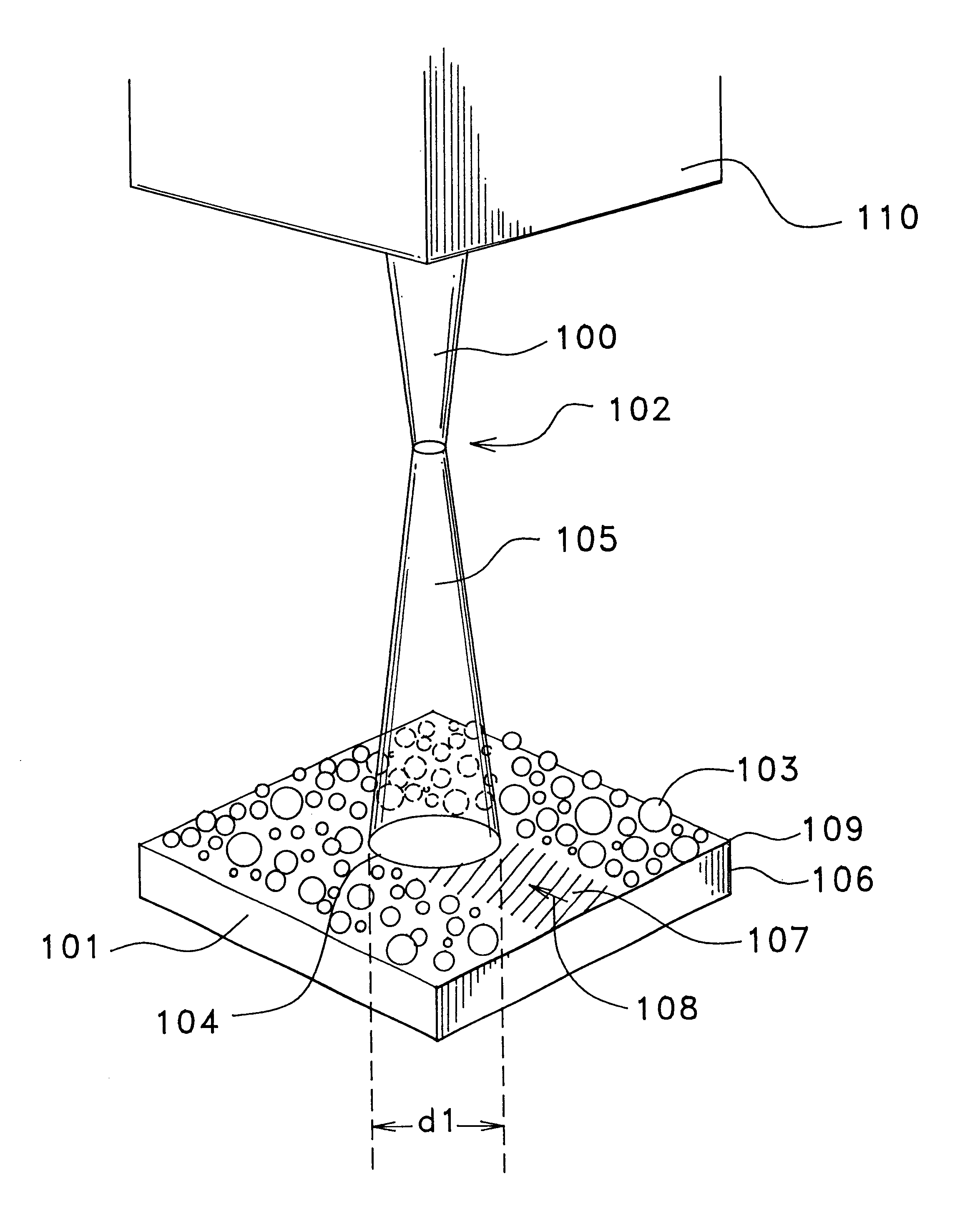
The marking materials and substrate described and illustrated in FIG. 1 above are employed, applying the marking materials electrostatically as liquid droplets. Application of the same laser beam producers markings which have more even edges, a smoother surface and more uniform thickness.

example c

HYPOTHETICAL EXAMPLE C

The marking materials and substrate described and illustrated in FIG. 5 above are employed, applying the marking materials electrostatically as dry particles. Application of the same laser beam producers markings which have more even edges, a smoother surface and more uniform thickness.

example d

HYPOTHETICAL EXAMPLE D

The marking materials and substrate described and illustrated in FIG. 5 above are employed, applying the marking materials electrostatically as liquid droplets. Application of the same laser beam producers markings which have more even edges, a smoother surface and more uniform thickness.

Before explaining the disclosed embodiment of the present invention in detail, it is to be understood that the invention is not limited in its application to the details of the particular arrangement shown, since the invention is capable of other embodiments. Also, the terminology used herein is for the purpose of description and not of limitation.


PUM

PropertyMeasurementUnit
Temperatureaaaaaaaaaa
Thicknessaaaaaaaaaa
Thicknessaaaaaaaaaa

Abstract

A method of radiantly marking substrates including metals, plastics, ceramic materials, glazes, glass ceramics, and glasses of any desired form, which comprises electrostatically applying to the material to be marked a variable thickness layer of marking material containing energy absorbing components and/or enhancers, then irradiating said layer with a radiant energy source such as a laser or diode based energy source such that the radiation is directed onto said layer, optionally in accordance with the form of the marking to be applied, preferably using a laser or diode based energy source of a wavelength which is sufficiently absorbed by the marking material so as to create a bonding of the marking material to the surface of the workpiece at the irradiated areas.

Description

FIELD OF INVENTIONThe present invention relates to a method of producing permanent, enhanced contrast and / or color markings formed as a new marking layer on top of substrates including glass, ceramic, porcelain, metal, and plastic. A laser beam or other suitable radiant energy source irradiates a marking medium having a glass frit containing an energy absorbing enhancer, or alternatively the marking medium can be a mixed metal oxide or a mixed organic pigment. This invention further relates to a method of producing permanent enhanced contrast and / or color markings formed as a new marking layer on top of both electrically conductive and non-conductive substrate materials by electrostatically coating said substrate materials and irradiating said coating with a laser beam in accordance with the form of a mark or decoration to be produced. In particular, this invention pertains to the application of laser marking materials in a controlled pattern of finely separated, charged coating par...

Claims


Application Information

Patent Timeline
IPC IPC(8): B41M5/26G06K1/12G06K1/00
CPCB41M5/262G06K1/126B41M5/267
Inventor HARRISON, PAUL WOLLCOTT
Owner THERMAX LLC
Why Eureka
Try Eureka