Electrosurgical apparatus having digestion electrode and methods related thereto

a technology of electrosurgical equipment and electrodes, which is applied in the field of electrosurgical equipment having digestion electrodes and related methods, can solve the problems of tissue desiccation or destruction at the contact point of the patient's tissue, damage to or destruction of tissue, and suffers in the field of electrosurgical equipment and procedures, so as to avoid or minimize current shorting, and promote plasma generation more aggressive

Inactive Publication Date: 2005-05-24
ARTHROCARE
View PDF262 Cites 308 Cited by
  • Summary
  • Abstract
  • Description
  • Claims
  • Application Information

AI Technical Summary

Benefits of technology

[0020]In another aspect, the present invention provides an electrosurgical probe having a fluid delivery element for delivering electrically conductive fluid to the active electrode(s) and the target site. The fluid delivery element may be located on the instrument, e.g., a fluid lumen or tube, or it may be part of a separate instrument. In an exemplary configuration the fluid delivery element includes at least one opening that is positioned around the active electrodes. Such a configuration provides an improved flow of electrically conductive fluid and promotes more aggressive generation of the plasma at the target site.
[0021]Alternatively, an electrically conductive fluid, such as a gel or liquid spray, e.g., saline, may be applied to the tissue. In arthroscopic procedures, the target site will typically already be immersed in a conductive irrigant, i.e., saline. In these embodiments, the apparatus may lack a fluid delivery element. In both embodiments, the electrically conductive fluid will preferably generate a current flow path between the active electrode(s) and the return electrode(s). In an exemplary embodiment, a return electrode is located on the instrument and spaced a sufficient distance from the active electrode(s) to substantially avoid or minimize current shorting therebetween and to shield the tissue from the return electrode at the target site.

Problems solved by technology

These electrosurgical devices and procedures, however, suffer from a number of disadvantages.
This current, however, may inadvertently flow along localized pathways in the body having less impedance than the defined electrical path.
This situation will substantially increase the current flowing through these paths, possibly causing damage to or destroying tissue along and surrounding this pathway.
One drawback with this configuration, however, is that the return electrode may cause tissue desiccation or destruction at its contact point with the patient's tissue.
Another limitation of conventional bipolar and monopolar electrosurgery devices is that they are not suitable for the precise removal (i.e., ablation) of tissue.
At the point of contact of the electric arcs with tissue, rapid tissue heating occurs due to high current density between the electrode and tissue.
The tissue is parted along the pathway of vaporized cellular fluid, inducing undesirable collateral tissue damage in regions surrounding the target tissue site.
In addition, conventional electrosurgical methods are generally ineffective for ablating certain types of tissue, and in certain types of environments within the body.
For example, loose or elastic connective tissue, such as the synovial tissue in joints, is extremely difficult (if not impossible) to remove with conventional electrosurgical instruments because the flexible tissue tends to move away from the instrument when it is brought against this tissue.
Since conventional techniques rely mainly on conducting current through the tissue, they are not effective when the instrument cannot be brought adjacent to or in contact with the elastic tissue for a long enough period of time to energize the electrode and conduct current through the tissue.
The use of electrosurgical procedures (both monopolar and bipolar) in electrically conductive environments can be further problematic.
However, the presence of saline, which is a highly conductive electrolyte, can cause shorting of the active electrode(s) in conventional monopolar and bipolar electrosurgery.
Such shorting causes unnecessary heating in the treatment environment and can further cause non-specific tissue destruction.
Conventional electrosurgical cutting or resecting devices also tend to leave the operating field cluttered with tissue fragments that have been removed or resected from the target tissue.
These tissue fragments make visualization of the surgical site extremely difficult.
Removing these tissue fragments can also be problematic.
Similar to synovial tissue, it is difficult to maintain contact with tissue fragments long enough to ablate the tissue fragments in situ with conventional devices.
However, the tissue fragments often clog the aspiration lumen of the suction instrument, forcing the surgeon to remove the instrument to clear the aspiration lumen or to introduce another suction instrument, which increases the length and complexity of the procedure.

Method used


Image

  • Electrosurgical apparatus having digestion electrode and methods related thereto
  • Electrosurgical apparatus having digestion electrode and methods related thereto
  • Electrosurgical apparatus having digestion electrode and methods related thereto

Examples


Embodiment Construction

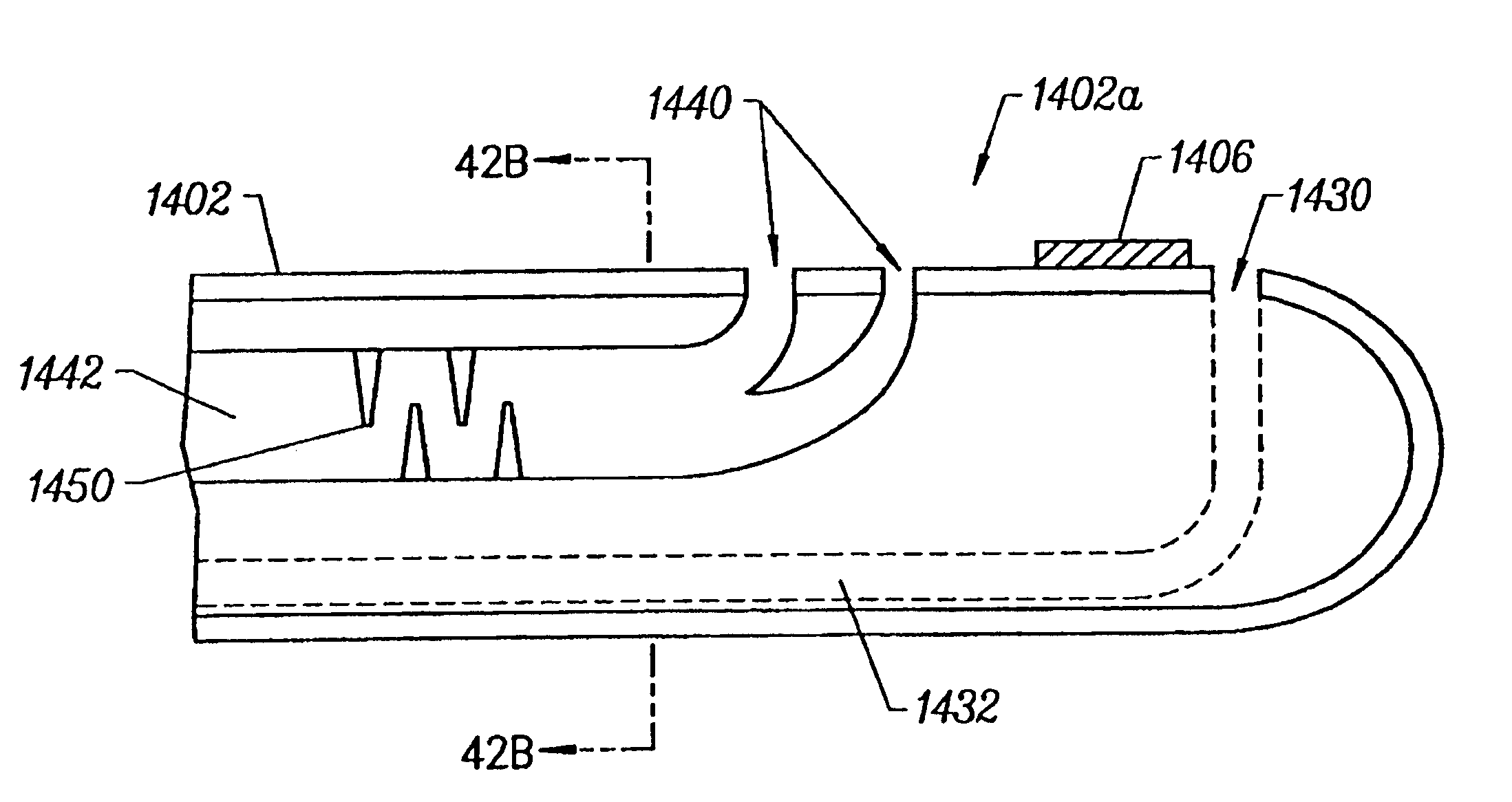
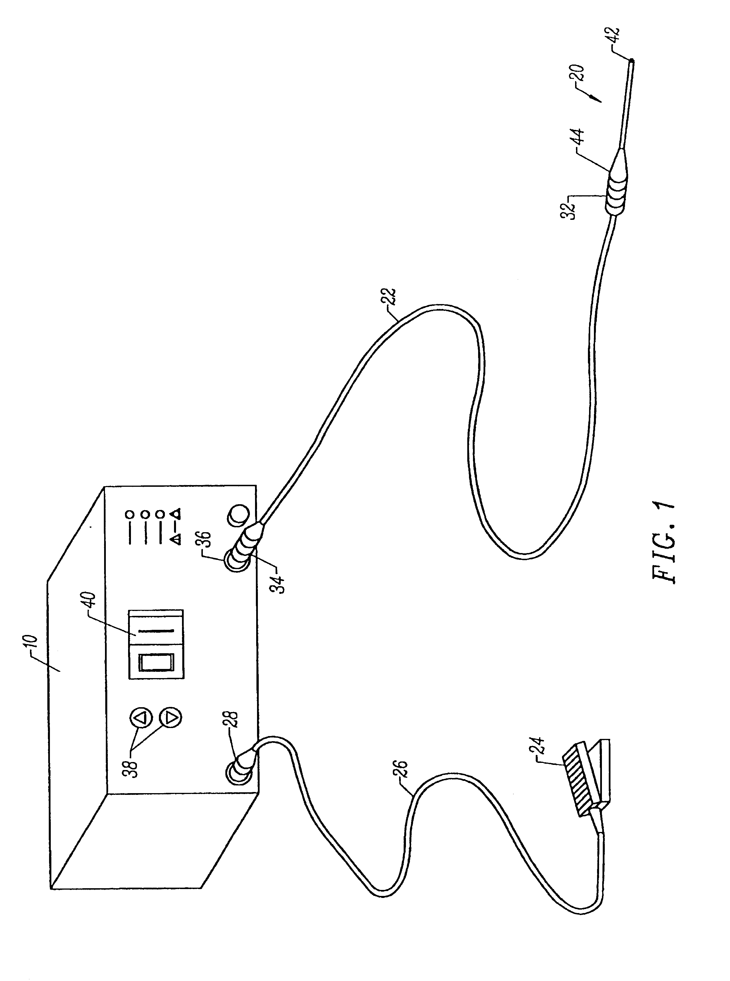
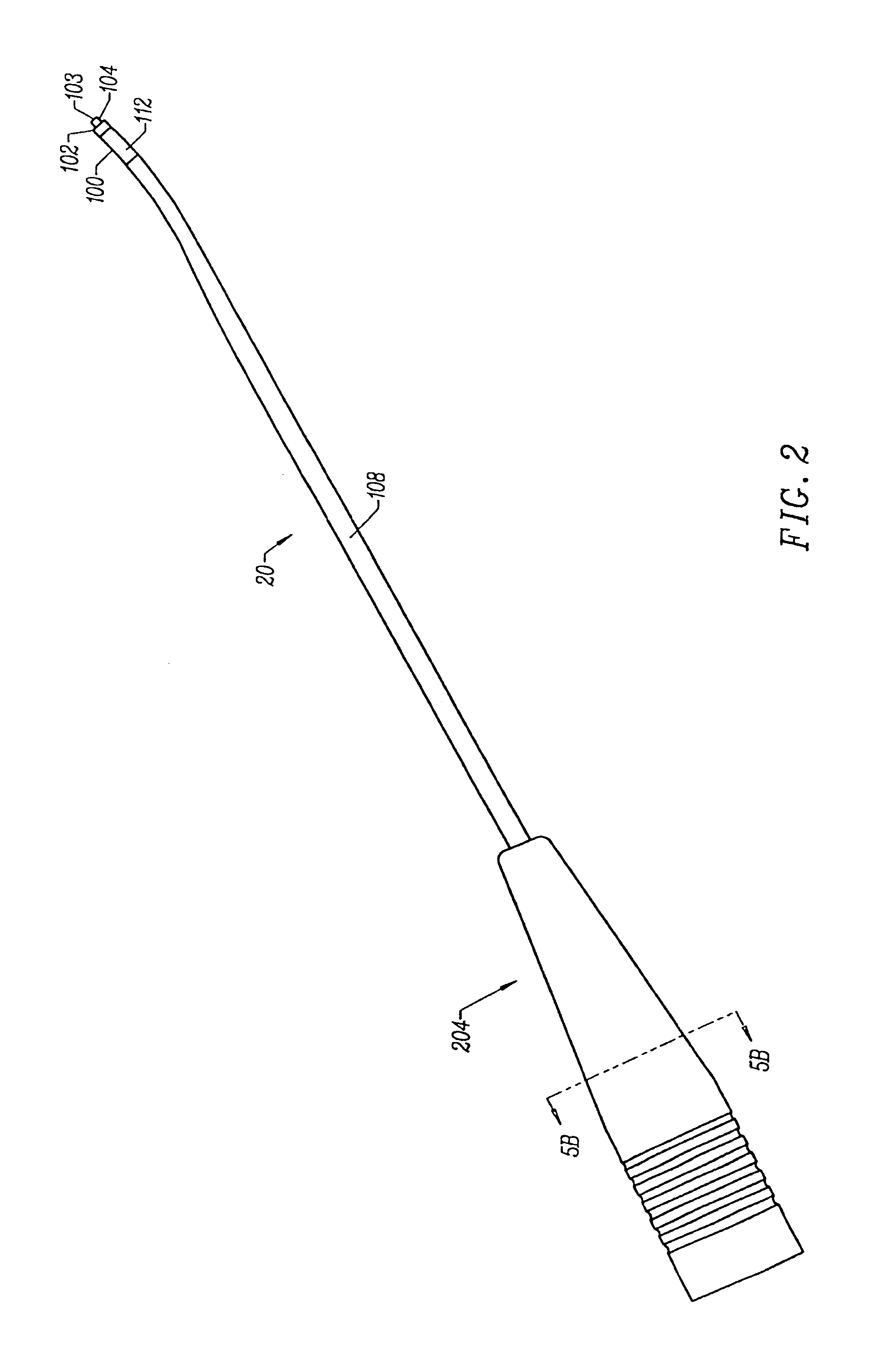
[0076]The present invention provides systems and methods for selectively applying electrical energy to a target location within or on a patient's body. The present invention is particularly useful in procedures where the tissue site is flooded or submerged with an electrically conductive fluid, such as arthroscopic surgery of the knee, shoulder, ankle, hip, elbow, hand or foot. In addition, tissues which may be treated by the system and method of the present invention include, but are not limited to, prostate tissue and leiomyomas (fibroids) located within the uterus, gingival tissues and mucosal tissues located in the mouth, tumors, scar tissue, myocardial tissue, collagenous tissue within the eye or epidermal and dermal tissues on the surface of the skin. Other procedures for which the present invention may be used include laminectomy / disketomy procedures for treating herniated disks, decompressive laminectomy for stenosis in the lumbosacral and cervical spine, posterior lumbosacr...


PUM

PropertyMeasurementUnit
distanceaaaaaaaaaa
angleaaaaaaaaaa
angleaaaaaaaaaa

Abstract

Methods and apparatus for resecting and ablating tissue at a target site of a patient, the apparatus including a probe having an elongate shaft. The shaft includes a shaft distal end portion and a shaft proximal end portion, and a resection unit located at the shaft distal end portion. The resection unit includes a resection electrode support and at least one resection electrode arranged on the resection electrode support. The at least one resection electrode includes a resection electrode head. The probe and resection electrode head are adapted for concurrent electrical ablation and mechanical resection of target tissue. The shaft may include at least one digestion electrode capable of aggressively ablating resected tissue fragments. At least one fluid delivery port on the shaft distal end portion may provide an electrically conductive fluid to the resection unit or to the target site. The shaft may include at least one aspiration port, located proximal to the resection unit, for aspirating excess or unwanted fluids and resected tissue fragments from the target site. The at least one aspiration port is coupled to an aspiration lumen. The at least one digestion electrode may be arranged within the aspiration lumen for ablation of tissue fragments therein. In use, the digestion and resection electrodes of the probe are coupled to a high frequency power supply. A surgical kit comprising the probe is also disclosed, together with a method of making the probe.

Description

RELATED APPLICATIONS[0001]The present invention claims priority from Provisional Patent Application No. 60 / 210,567, filed Jun. 9, 2000, and is a continuation-in-part of U.S. patent application No. 09 / 197,013, filed Nov. 20, 1998, which is a continuation-in-part of U.S. patent application No. 09 / 010,382, filed Jan. 21, 1998, which is a continuation-in-part of U.S. patent application No. 08 / 990,374, filed on Dec. 15, 1997, which is a continuation-in-part of U.S. patent application No. 08 / 485,219, filed on Jun. 7, 1995, now U.S. Pat. No. 5,697,281, which is a continuation-in-part of PCT International Application, U.S. National Phase Serial No. PCT / US94 / 05168, filed on May 10, 1994, now U.S. Pat. No. 5,697,909, which was a continuation-in-part of U.S. patent application Ser. No. 08 / 059,681, filed on May 10, 1993, the complete disclosures of which are incorporated herein by reference for all purposes. The present invention also derives priority from Provisional Patent Application 60 / 062,...

Claims


Application Information

Patent Timeline
Patent Type & Authority Patents(United States)
IPC IPC(8): A61B18/12A61B18/14A61B18/00A61F2/02A61M1/00A61B17/00
CPCA61B18/1206A61B18/1402A61B18/148A61B18/1482A61B18/1485A61B18/149A61F2/2493A61B18/1492A61B2017/00026A61B2017/00084A61B2017/00101A61B2017/00247A61B2018/00029A61B2018/00083A61B2018/00095A61B2018/00119A61B2018/0016A61B2018/00178A61B2018/00267A61B2018/00327A61B2018/00392A61B2018/00434A61B2018/0044A61B2018/00577A61B2018/00583A61B2018/00589A61B2018/00601A61B2018/00666A61B2018/00678A61B2018/00702A61B2018/0072A61B2018/00726A61B2018/00779A61B2018/00791A61B2018/00827A61B2018/00875A61B2018/00982A61B2018/00988A61B2018/1213A61B2018/124A61B2018/1253A61B2018/126A61B2018/1273A61B2018/1407A61B2018/1467A61B2018/1472A61B2018/162A61B2018/165A61B2218/002A61B2218/007A61B18/14
Inventor WOLOSZKO, JEANDAVISON, TERRY S.HOVDA, DAVID C.THAPLIYAL, HIRA V.EGGERS, PHILIP E.
Owner ARTHROCARE
Why Eureka
Try Eureka