Polishing apparatus and dressing method for polishing tool

a technology of polishing apparatus and dressing method, which is applied in the direction of manufacturing tools, lapping machines, and abrasive surface conditioning devices, etc., can solve the problems of unstable polishing rate, reduced throughput, and gradual reduction of polishing rate, so as to achieve satisfactory dressing, enhance the effect of dressing, and improve the effect of dressing

Inactive Publication Date: 2005-05-31
EBARA CORP
View PDF6 Cites 68 Cited by
  • Summary
  • Abstract
  • Description
  • Claims
  • Application Information

AI Technical Summary

Benefits of technology

[0024]According to a fifteenth feature thereof, the present invention is applied to a method of dressing a polishing surface of a polishing tool. The polishing surface includes abrasive particles and a binder for bonding together the abrasive particles, and is used in a polishing step in which the polishing surface is pressed against a substrate and moved relative thereto to polish the substrate. The dressing method includes a light ray irradiation step of irradiating the polishing surface of the polishing tool with light rays for weakening a bond force of the binder. The light ray irradiation step is performed during the polishing step, in which the substrate is polished with the polishing tool, and also performed between one polishing step and a subsequent polishing step. With this arrangement, the light ray irradiation step is performed simultaneously with the polishing step and also performed between the one polishing step and the subsequent polishing step. Therefore, even if progress of dressing of the polishing surface is slow, the polishing surface can be dressed satisfactorily.
[0025]According to a sixteenth feature of the present invention, the dressing method has the fifteenth feature. Further, the polishing step is performed by rotating the polishing tool. A number of revolutions of the polishing tool during a time when the polishing step is not performed is not more than 10 revolutions per minute. With this arrangement, during the time when the polishing step is not performed, the polishing tool is rotated at a low speed even more suitable for dressing at which a dressing accelerator or the like supplied to the polishing surface during dressing is unlikely to be splashed from the polishing surface. Thus, an effect of dressing can be enhanced.
[0026]According to a seventeenth feature of the present invention, the dressing method has the fifteenth or sixteenth feature. Further, when a rate of dressing in the light ray irradiation step is high, the light ray irradiation step performed simultaneously with the polishing step is intermittently performed. When a rate of dressing is low, the light ray irradiation step is further performed between the one polishing step and the subsequent polishing step. With this arrangement, dressing time is shortened or lengthened according to whether the rate of dressing is high or low, so that stock removal during dressing of the polishing surface can be adjusted to an appropriate value.

Problems solved by technology

However, in a semiconductor wafer polishing process using a polishing tool, the polishing rate reduces gradually although it is high immediately after the polishing tool has been dressed.
Thus, the polishing rate is unstable.
However, if the polishing tool is dressed before each polishing operation, because a predetermined period of time is required to perform dressing, throughput reduces and productivity degrades in practical application.
Furthermore, a dresser having fixed diamond particles that is employed in general chemical / mechanical polishing involves a problem in that diamond particles may fall off onto a polishing surface.
If such foreign substances are present on a polishing surface, it is difficult to increase a polishing rate and to ensure stability therefor even if free abrasive particles are sufficiently generated from a fixed abrasive.

Method used


Image

  • Polishing apparatus and dressing method for polishing tool
  • Polishing apparatus and dressing method for polishing tool
  • Polishing apparatus and dressing method for polishing tool

Examples


first embodiment

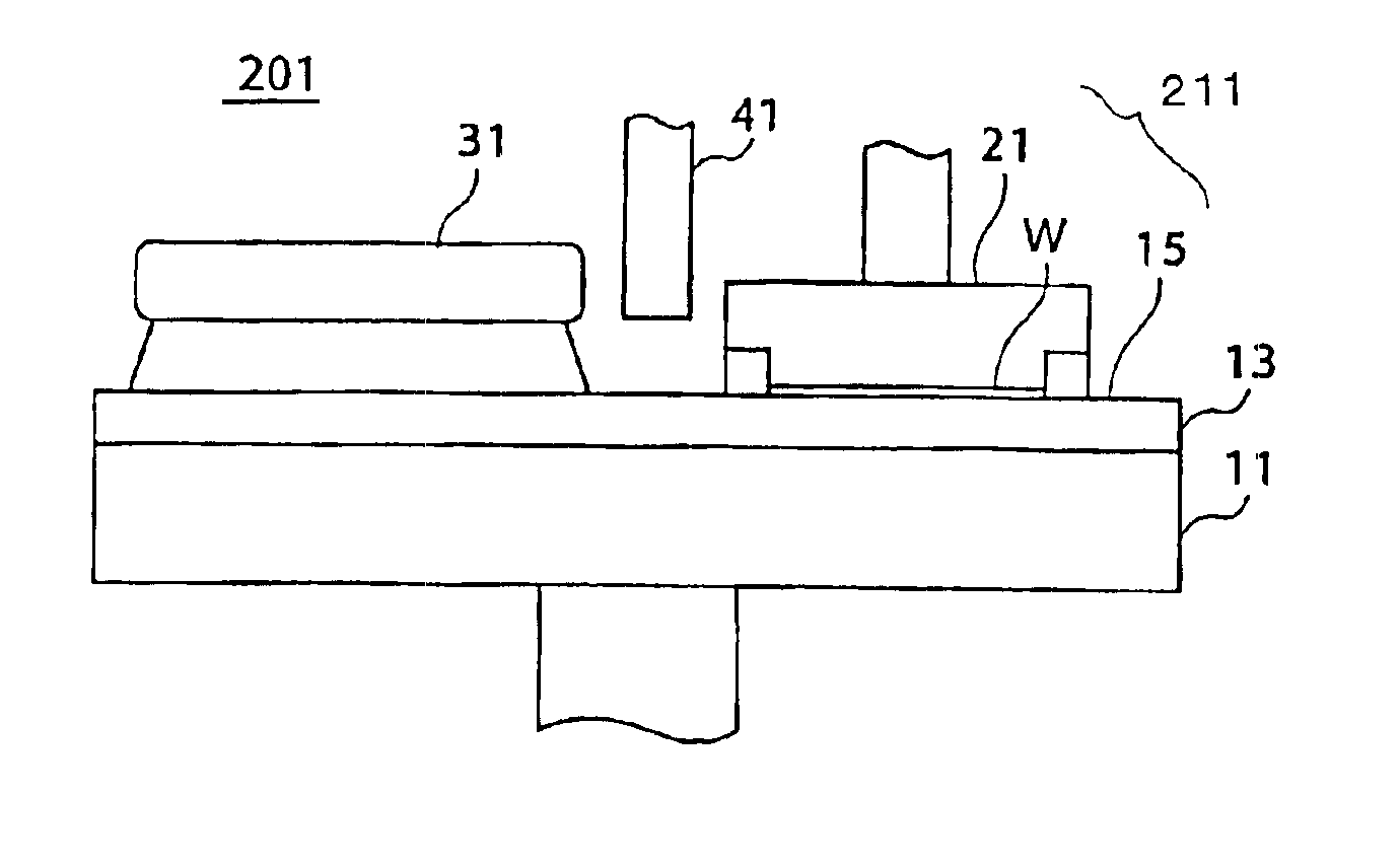
[0046]FIG. 1 is a schematic front view showing a polishing apparatus 201 according to the present invention. The polishing apparatus 201 has a rotating turntable 11 and a fixed abrasive 13 provided on the turntable 11. In this embodiment, the fixed abrasive 13 constituting a polishing tool is formed by including abrasive particles (not shown) and a binder (not shown) for fixing (bonding) together the abrasive particles.

[0047]Examples of substances usable as materials for the abrasive particles of the fixed abrasive 13 are silicon oxide (SiO2), alumina (Al2O3), cerium oxide (CeO2), silicon carbide (SiC), zirconia (ZrO), iron oxides (FeO, Fe3O4), manganese oxides (MnO2, Mn2O3), magnesium oxide (MgO), calcium oxide (CaO), barium oxide (BaO), zinc oxide (ZnO), barium carbonate (BaCO3), diamond (C) and titanium oxide (TiO2).

[0048]Examples of usable binder materials are thermosetting resins such as epoxies (EP), phenols (PF), ureas (UF), melamines (MF), unsaturated polyesters (UP), silico...

second embodiment

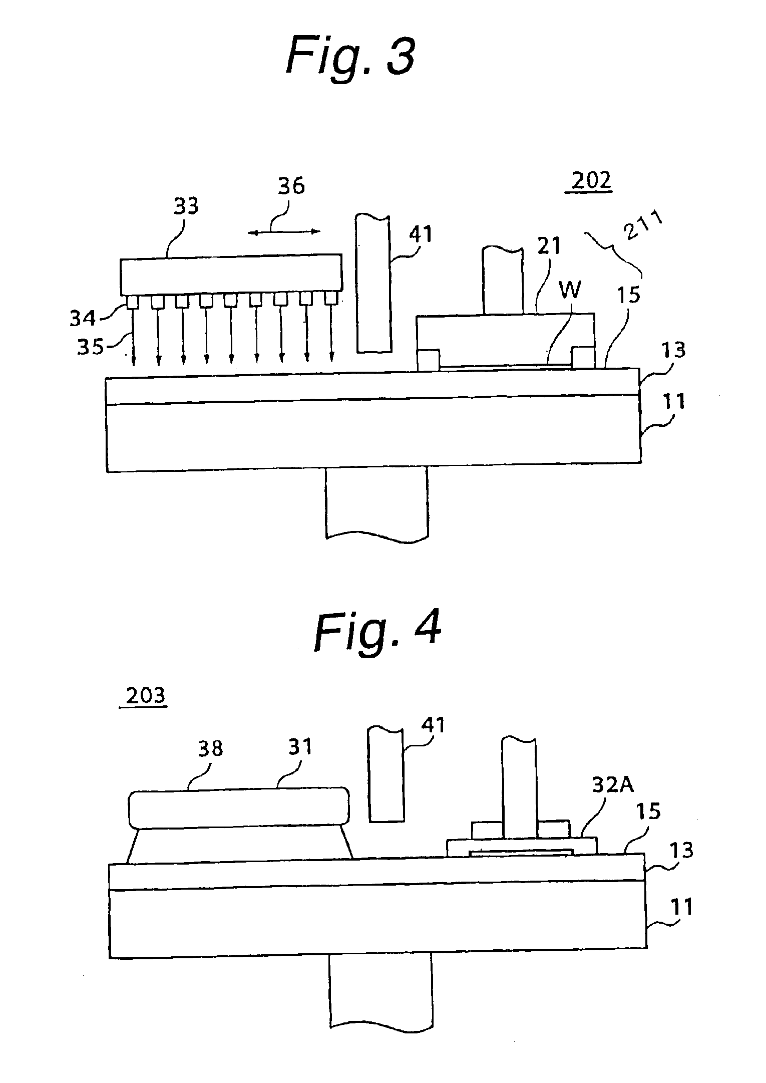
[0055]FIG. 3 is a schematic front view showing a polishing apparatus 202 according to the present invention. In the polishing apparatus 202, a laser source 33 is used as a light source to apply laser beams to fixed abrasive 13. The laser source 33 has a large number of laser beam outlets 34 to apply laser beams 35 thoroughly to an irradiated part (polishing surface 15) of the fixed abrasive 13 (with a circular planar configuration). The laser source 33 is capable of oscillating in directions indicated by double-headed arrow 36 in the figure (in horizontal directions parallel to a radial direction of the polishing surface 15). Thus, it is possible to avoid local concentration of laser beams 35 and, at the same time, possible to provide a high energy density to a surface (polishing surface 15) of the fixed abrasive 13 by irradiation with intense laser beams 35. Accordingly, free abrasive particles can be generated efficiently from the fixed abrasive. That is, a dressing effect can be ...

third embodiment

[0084]FIG. 4 shows a polishing apparatus 203 having a dresser 32A including diamond particles as a waste matter removing device according to the present invention. The polishing apparatus 203 includes a dressing mechanism 38 having a light source 31 to perform dressing by light irradiation. In the polishing apparatus 203, waste matter unrelated to polishing, including the above-described incompletely dissolved resin, can be scraped off or eliminated by pressing the dresser 32A against polishing surface 15 of fixed abrasive 13. Thus, polishing abrasive particles can be exposed even more effectively, and hence efficient polishing can be realized. Further, if the incompletely dissolved resin is scraped off, a surface condition that is at least homogeneous can be reproduced on the polishing surface 15. Thus, it is possible to maintain a uniform surface condition.


PUM

PropertyMeasurementUnit
pressureaaaaaaaaaa
bond energiesaaaaaaaaaa

Abstract

In a polishing apparatus, a polishing tool including abrasive particles and a binder for bonding together the abrasive particles is pressed against a substrate to polish the substrate. The polishing apparatus has a light source for irradiating a polishing surface with light rays for weakening a bond force of the binder for bonding together the abrasive particles, and a waste matter removing mechanism for forcefully removing waste matter produced by polishing or waste matter produced by irradiation. By irradiating the polishing surface with the light rays, dressing of the polishing surface is performed, and products resulting from dressing and the like are removed. The polishing apparatus supplies abrasive particles to the polishing surface stably by dressing and allows high-speed polishing of the substrate.

Description

REFERENCE TO RELATED APPLICATION[0001]This is a continuation of International Application PCT / JP03 / 08766, filed Jul. 10, 2003, the contents of which are incorporated herein by reference. This application further claims priority on Japanese Application 2002-204498, filed Jul. 12, 2002.TECHNICAL FIELD[0002]The present invention relates to a polishing apparatus having a light source for dressing (regenerating) a polishing tool by irradiation with light rays, and further having a waste matter removing device for removing waste matter (contamination) produced by dressing and the like. The present invention also relates to a dressing method for a polishing tool that has an addressing step (light ray irradiation step) of dressing the polishing tool by irradiation with light rays, and a waste matter removing step of removing waste matter produced by the dressing and the like.BACKGROUND ART[0003]With rapid progress of technology to fabricate high-integration semiconductor devices in recent y...

Claims


Application Information

Patent Timeline
Patent Type & Authority Patents(United States)
IPC IPC(8): B24B37/04B24B53/007
CPCB24B37/245B24B53/017Y10S451/91
Inventor KOJIMA, SHUNICHIROHIROKAWA, KAZUTOKODERA, AKIRA
Owner EBARA CORP
Why Eureka
Try Eureka