Exposure apparatus with laser device

Inactive Publication Date: 2005-05-31
NIKON CORP
View PDF15 Cites 114 Cited by
  • Summary
  • Abstract
  • Description
  • Claims
  • Application Information

AI Technical Summary

Benefits of technology

[0036]The exposure apparatus of the present invention further includes an illumination system which irradiates a mask with ultraviolet light from the laser device, and a projection optical system which projects an image of a pattern of the mask onto a substrate, wherein the substrate is exposed with the ultraviolet light which has passed through the pattern of the mask. With the laser device of the present invention being used, the exposure apparatus can be miniaturized overall, and the maintainability thereof is increased.
[0037]In addition, in a first exposure method of the present invention, the ultraviolet light from the laser device is used as alignment light for an exposure apparatus of, for example, a TTR (through the reticle) method type, of the exposure apparatus. The alignment light can be formed to substantially be continuous light, thereby facilitating the alignment.
[0038]A se

Problems solved by technology

Second, when the exposure light is ultraviolet light having a wavelength of 300 nm or shorter, an optical material which can be used for a reflector member (lens) of a projection optical system is limited, and hence the difficulty increases for compensation of the chromatic aberration.
This arises various problems.
For example, the transmittance of an optical component tends to vary because of so-called compaction and the like, complicated maintenance is required and hence costs are increased.
In this connection, these methods arises other problems.
For example, the aforementioned adjustment requires a sensitive arrangement; and in proportion to the increase in the constituent laser elements, the complexity of the configuration needs to be increased to cause the overall devices to oscillate with the same wavelength.
However, the

Method used


Image

  • Exposure apparatus with laser device
  • Exposure apparatus with laser device
  • Exposure apparatus with laser device

Examples


first embodiment

[0054]Hereinbelow, a preferred first embodiment according to the present invention will be described with reference to the accompanying drawings. The present embodiment represents a configuration in which the present invention is applied to an ultraviolet light generator that can be used as an ultraviolet-region exposure light source of a projection exposure apparatus such as a stepper method or a step-and-scan method or as a light source for alignment and various tests.

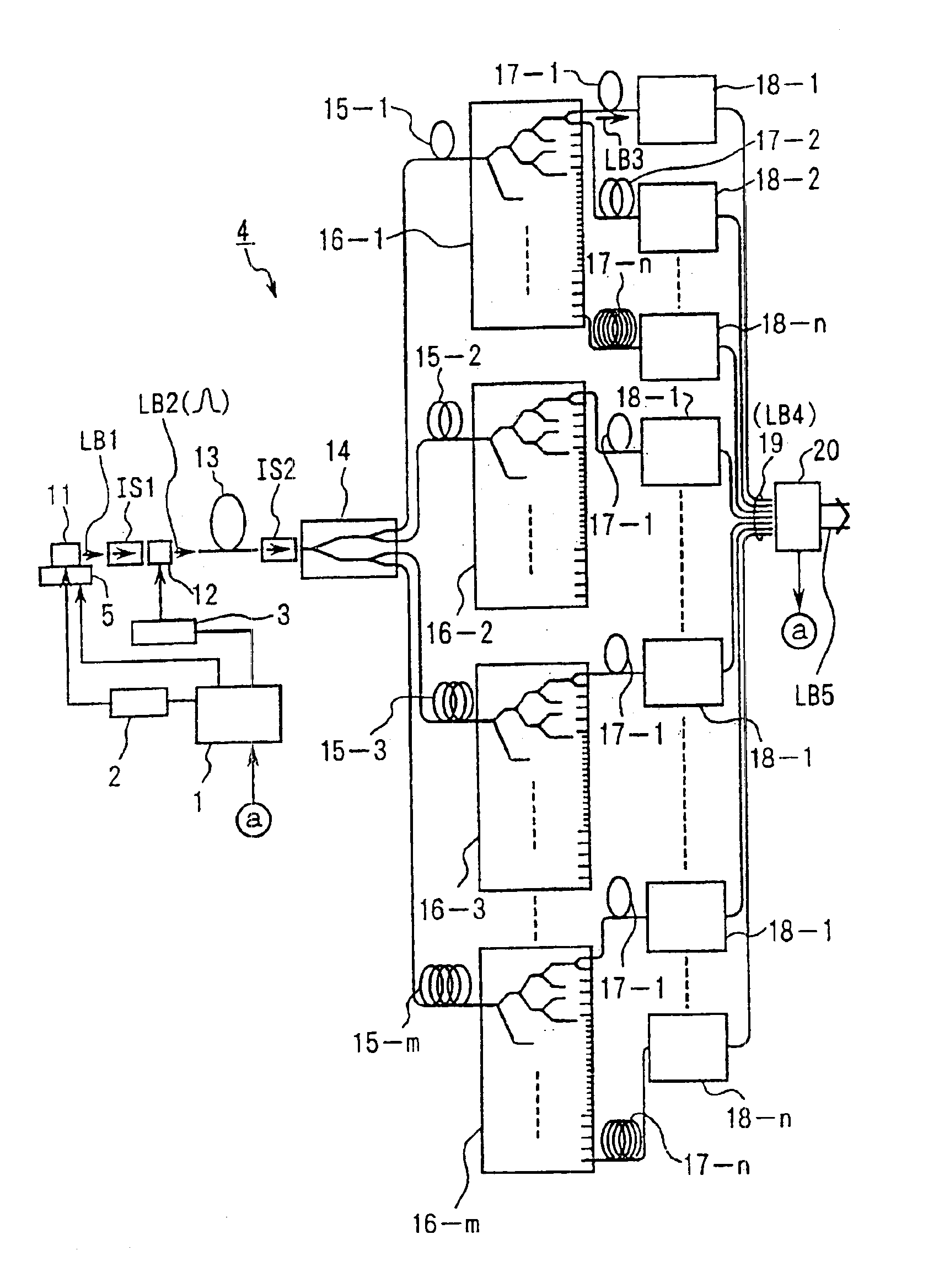
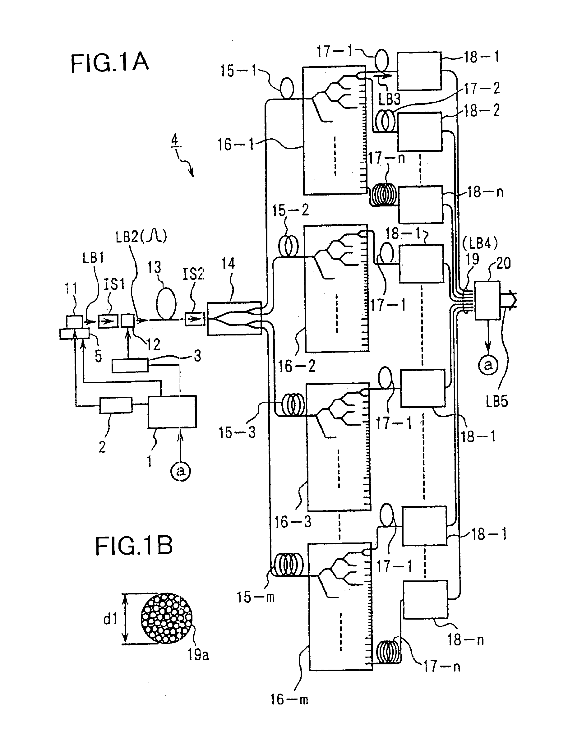
[0055]FIG. 1A shows an ultraviolet light generator according to the present embodiment. Referring to FIG. 1A, a single wavelength oscillatory laser 11, which is provided as a laser light generation section, generates a laser beam LB1 that is formed of, for example, a continuous wave (CW) having a narrow spectral width and that has a wavelength of 1.544 μm. The laser beam LB1 is incident on an optical modulating device 12, which is provided as an optical modulator, via an isolator IS1 provided for blocking reverse lig...

second embodiment

[0124]Hereinbelow, the present invention will be described with reference to FIGS. 7 to 9. The present embodiment is different from the embodiment shown in FIG. 1A in portions of the configurations from the single wavelength oscillatory laser 11 to the optical fiber amplifier 13. A description will therefore be made regarding the different portions.

[0125]FIG. 7 shows essential portions of the present embodiment. Referring to FIG. 7, a laser beam LB1 having a wavelength of 1.544 μm (which hereinbelow will be represented by λ1) that has been output from the single wavelength oscillatory laser 11 is incident on a wavelength division multiplexing device (WDM device) 52 through an optical fiber 53A. A laser beam LBR having a wavelength λ2, which is different from the laser beam having the wavelength λ1 that has been output from a semiconductor laser 51 provided as an auxiliary light source, is incident on the WDM device 52 through an optical fiber 53B. A laser beam formed of the laser be...

third embodiment

[0131]Hereinbelow, the present invention will be described with reference to FIG. 10. Also the present embodiment is different from the embodiment shown in FIG. 1A in portions of the configurations from the single wavelength oscillatory laser 11 to the optical fiber amplifier 13. A description will therefore be made regarding the different portions.

[0132]FIG. 10 shows essential portions of the present embodiment. Referring to FIG. 10, a laser beam LB1 (which is assumed to be linear polarization light) having a wavelength of 1.544 μm that has been output from the single wavelength oscillatory laser 11 is incident on a polarized-wave combining device 55 for coaxially combining two light beams of different polarized states, and a laser beam LBP is incident on the polarized-wave combining device 55. The laser beam LBP has a wavelength of 1.544 μm, is output from a semiconductor laser 54 provided as an auxiliary light source, and is linearly polarized in the direction perpendicular to th...


PUM


Abstract

An exposure apparatus has a laser device that is small, easy to maintain, and capable of producing an output that is unlikely to be affected by optical surges occurring in the beginning of operation. A single-wavelength laser oscillator (11) supplies a laser beam (LB1) to a fiber optic amplifier (13) through an optical modulator (12). The amplified laser beam is split by splitters (14, 16-1 to 16-m), amplified by optical amplifier units (18-1 to 18-n) and supplied through a fiber bundle (19) to a wavelength converter (20), which in turn converts the split beams into ultraviolet laser radiation (LB5) for use as exposure light. The optical modulator (12) outputs light pulses during the generation of ultraviolet light. The optical modulator (12) also produces laser radiation during the absence of ultraviolet light, but the laser radiation has substantially the same average output and a considerably low peak compared with that during the generation of ultraviolet light.

Description

[0001]This application is the national phase under 35 U.S.C. 371 of prior PCT International Application No. PCT / JP00 / 06132 which has an International filing date of Sep. 8, 2000 which designated the United States of America, the entire contents of which are hereby incorporated by reference.TECHNICAL FIELD[0002]The present invention relates to an exposure apparatus including a laser device which generates ultraviolet light. More specifically, the present invention is preferably used as an exposure apparatus used in a photolithography process for manufacturing microdevices, such as semiconductor devices, image pickup devices (such as CCDs), liquid crystal display devices, plasma display devices, and thin-film magnetic heads.BACKGROUND ART[0003]For example, an exposure apparatus used in a photolithography process for manufacturing a semiconductor integrated circuit optically reduces and projectively exposes a circuit pattern accurately rendered on a reticle (photomask) used as a mask, ...

Claims


Application Information

Patent Timeline
IPC IPC(8): G03F7/20G02F1/35G02F1/37
CPCG02F1/37G03F7/70041G03F7/70025G02F2001/354G02F1/354
Inventor OHTSUKI, TOMOKO
Owner NIKON CORP
Why Eureka
Try Eureka