Reinforced carbon nanotubes

a technology of reinforced carbon nanotubes and carbon nanotubes, which is applied in the direction of synthetic resin layered products, chemical vapor deposition coatings, natural mineral layered products, etc., can solve the problems of reduced load bearing ability, “sword-in-sheath” type failure mechanism, and no significant improvement in mechanical properties after such modification, and achieves improved mechanical properties and high strength

Inactive Publication Date: 2005-06-28
BOSTON COLLEGE
View PDF3 Cites 56 Cited by
  • Summary
  • Abstract
  • Description
  • Claims
  • Application Information

AI Technical Summary

Benefits of technology

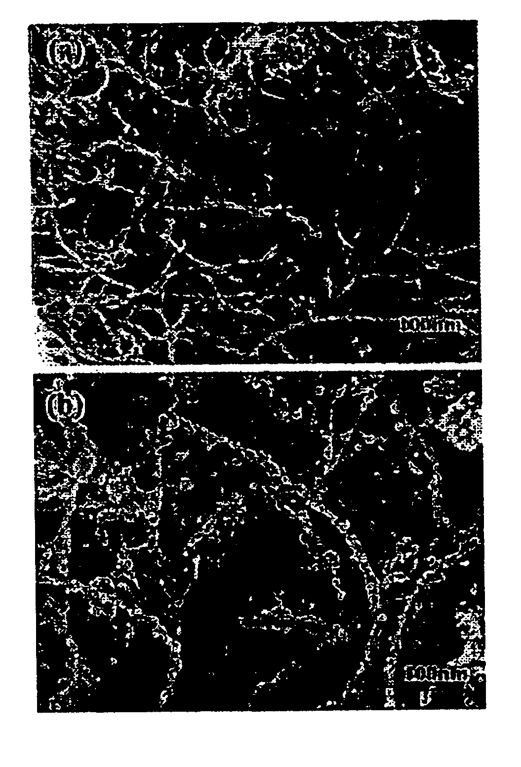
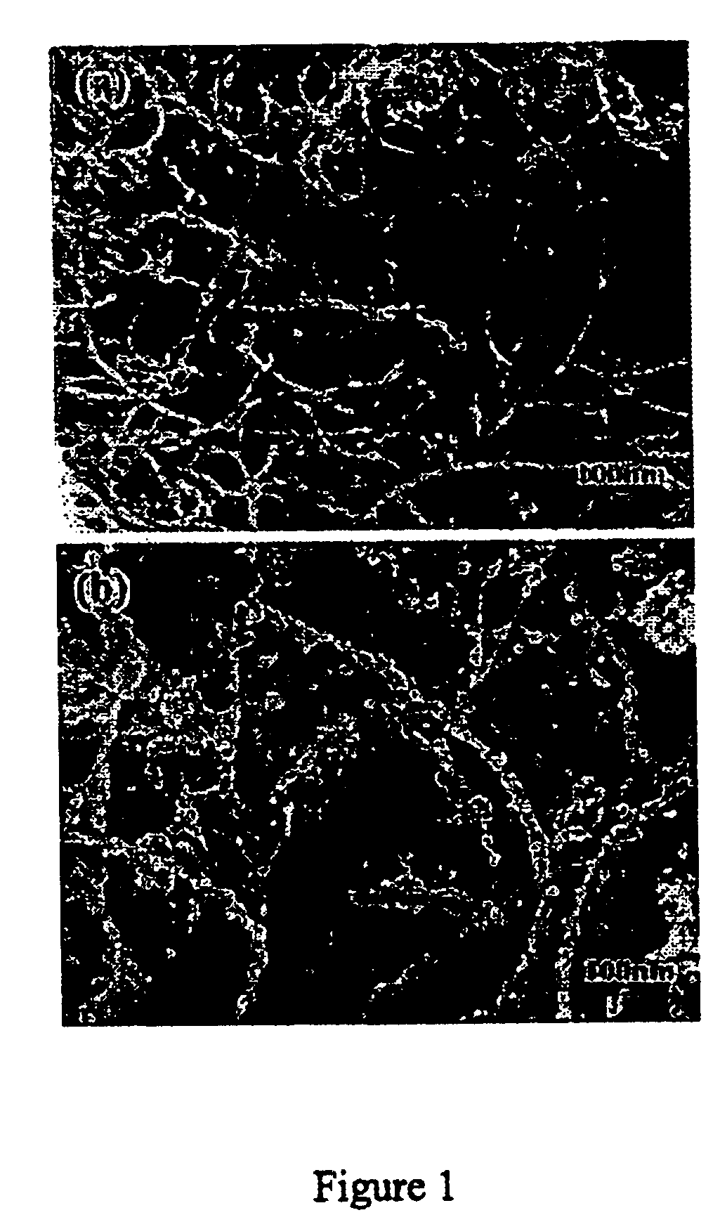
[0006]The present invention provides CNTs comprising a plurality of microparticulate carbide or nitride material that provide a reinforcing effect on the CNT matrix, thereby conferring improved mechanical properties in the composite materials comprising them as reinforcing fillers. In particular, the present invention provides microparticulate carbide reinforced CNTs comprising boron carbide nanolumps formed on the surface of CNTs. The present invention also provides a method of producing microparticulate carbide reinforced CNTs. Specifically, the present invention provides the use of microparticulate carbide reinforced CNTs having boron carbide nanolumps formed on the surface of the CNTs to enable their use as reinforcing composite fillers in producing high strength composite materials.

Problems solved by technology

Multi-walled CNTs have a tendency to pull out of, or slip from the matrix material, resulting in reduced load bearing ability.
This is attributed to the fact that the interface between the matrix material and nanotube layers is very weak, thereby causing a “sword-in-sheath” type failure mechanism.
However, no significant improvement in mechanical properties has been observed after such modification.
The bonding between the coating materials and CNTs is, however, not strong enough to result in efficient load transfer.

Method used


Image

  • Reinforced carbon nanotubes
  • Reinforced carbon nanotubes
  • Reinforced carbon nanotubes

Examples


example 1

Synthesis of Reinforced CNTs Having Boron Carbide (BxCy ) Nanolumps Formed Substantially on the Surface of the CNTs

[0067]The multi-wall CNTs were grown by catalytic chemical vapor deposition method (see Li, et al., Appl. Phys. A: Mater. Sci. Process, 73, 259 (2001), the contents of which is incorporated herein by reference in its entirety) and purified by hydrofluoric acid (HF). Magnesium diboride (MgB2), a new superconducting material, is used as the source of boron. The synthesis of magnesium diboride (MgB2) can be synthesised by combining elemental magnesium and boron in a sealed (Ta) tube in a stoichiometric ratio and sealed in a quartz ampule, placed in a box furnace at a temperature of about 950° C. for about 2 hours. Powder MgB2 with average grain size of about 1 micrometer decomposes at a temperature of about 600° C. Thermally decomposed boron is more chemically reactive so the solid-state reaction can be performed at relatively low temperatures. The nanotubes were mixed gen...

example 2

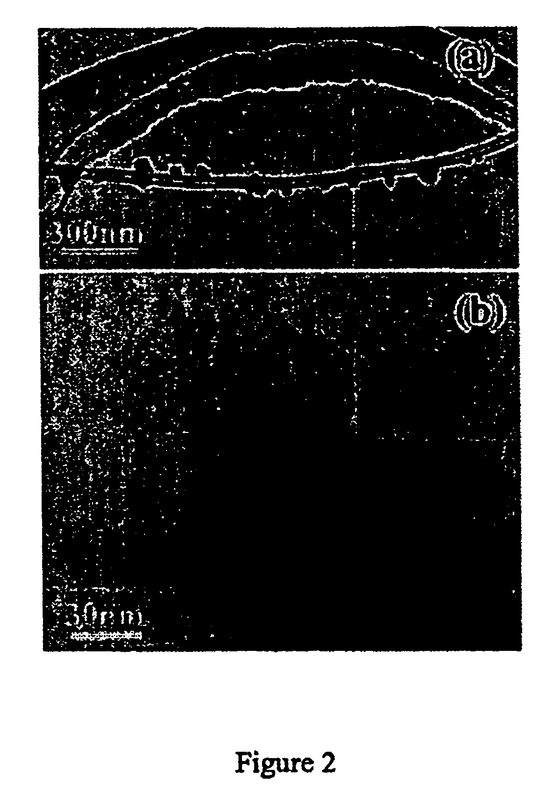
Determining the Composition of BxCy Nanolumps

[0068]In order to find out whether the nanolumps are boron carbide, a high-resolution transmission electron microscopic (HRTEM) image of a nanolump is taken and shown in FIG. 3(a). The carbon nanotube nature has been preserved after the reaction. The BxCy nanolump is crystalline. FIG. 3(b) is an enlarged HRTEM image of the top part of FIG. 3(a). FIG. 3(c) shows a fast-Fourier transformation (FFT) image of the HRTEM image shown in FIG. 3(b). The diffraction pattern obtained from FFT (FIG. 3(c)) is indexed as one from zone axis ({overscore (1)}11) of B4C. Structure parameters of B4C for the indexing are space group R3m: (166) and lattice parameters, a=0.56 nm, c=1.21 nm. As shown in FIG. 3(b), the simulated HRTEM image using parameters defocus −30 nm and thickness 20 nm also matches with experimental image very well. Although no boron was detected by the EDS analysis, it is reasonable to draw a conclusion that the nanolumps are of the formu...

example 3

Preparation of Catalyst Substrate for Synthesis of Linear CNTs

[0069]Mesoporous silica containing iron nanoparticles were prepared by a sol-gel process by hydrolysis of tetraethoxysilane (TEOS) in the presence of iron nitrate in aqueous solution following the method described by Li et al. (Science, (1996), Vol. 274, 1701-3) with the following modification. The catalyst gel was dried to remove excess water and solvents and calcined for about 10 hours at about 450° C. and about 10−2 torr to give a silica network with substantially uniform pores containing iron oxide nanoparticles that are distributed within. The catalyst gel is then ground into a fine, micro-particulate powder either mechanically using a ball mill or manually with a pestle and mortar. The ground catalyst particles provide particle sizes that range between about 0.1 μm and about 100 μm under the grinding conditions.


PUM

PropertyMeasurementUnit
diameteraaaaaaaaaa
diameteraaaaaaaaaa
gas pressureaaaaaaaaaa

Abstract

The present invention relates generally to reinforced carbon nanotubes, and more particularly to reinforced carbon nanotubes having a plurality of microparticulate carbide or oxide materials formed substantially on the surface of such reinforced carbon nanotubes composite materials. In particular, the present invention provides reinforced carbon nanotubes (CNTs) having a plurality of boron carbide nanolumps formed substantially on a surface of the reinforced CNTs that provide a reinforcing effect on CNTs, enabling their use as effective reinforcing fillers for matrix materials to give high-strength composites. The present invention also provides methods for producing such carbide reinforced CNTs.

Description

RELATED APPLICATIONS[0001]This application claims the benefit of U.S. Provisional Application Ser. No. 60 / 347,808, filed on Jan. 11, 2002, which is hereby incorporated herein by reference in its entirety.GOVERNMENT SUPPORT[0002]The present invention was made with partial support from The US Army Natick Soldier Systems Center (DAAD, Grant Number 16-00-C-9227), Department of Energy (Grant Number DE-FG02-00ER45805) and The National Science Foundation (Grant Number DMR-9996289)FIELD OF THE INVENTION[0003]The present invention relates generally to reinforced carbon nanotubes, and more particularly to reinforced carbon nanotubes having a plurality of microparticulate carbide materials formed substantially on the surface of such reinforced carbon nanotubes composite materials.BACKGROUND OF THE INVENTION[0004]Reinforcing fillers are usually added to a matrix material to form high-strength composites. In order for the resulting composites to be useful, the reinforcing fillers must have a hig...

Claims


Application Information

Patent Timeline
Patent Type & Authority Patents(United States)
IPC IPC(8): D01F9/12D01F11/00D01F11/12
CPCB82Y30/00C01B31/0253C04B35/62847C04B35/6286C04B35/62863C04B35/62892C04B35/62897D01F9/12D01F11/12B82Y40/00Y10T428/2918C01B2202/06C04B2235/5268C04B2235/5288Y10S977/752Y10T428/2975Y10T428/292Y10T428/2982Y10T428/2913Y10T428/30Y10T428/25C01B32/168
Inventor REN, ZHIFENWEN, JIAN GUOLAO, JING Y.LI, WENZHI
Owner BOSTON COLLEGE
Why Eureka
Try Eureka