Rectangular cathodic arc source and method of steering an arc spot
a technology of cathodic arc and source, which is applied in the direction of vacuum evaporation coating, electrolysis components, coatings, etc., to achieve the effects of greater coating area, uniform coating, and better distribution of cathodic evapora
- Summary
- Abstract
- Description
- Claims
- Application Information
AI Technical Summary
Benefits of technology
Problems solved by technology
Method used
Image
Examples
example 1
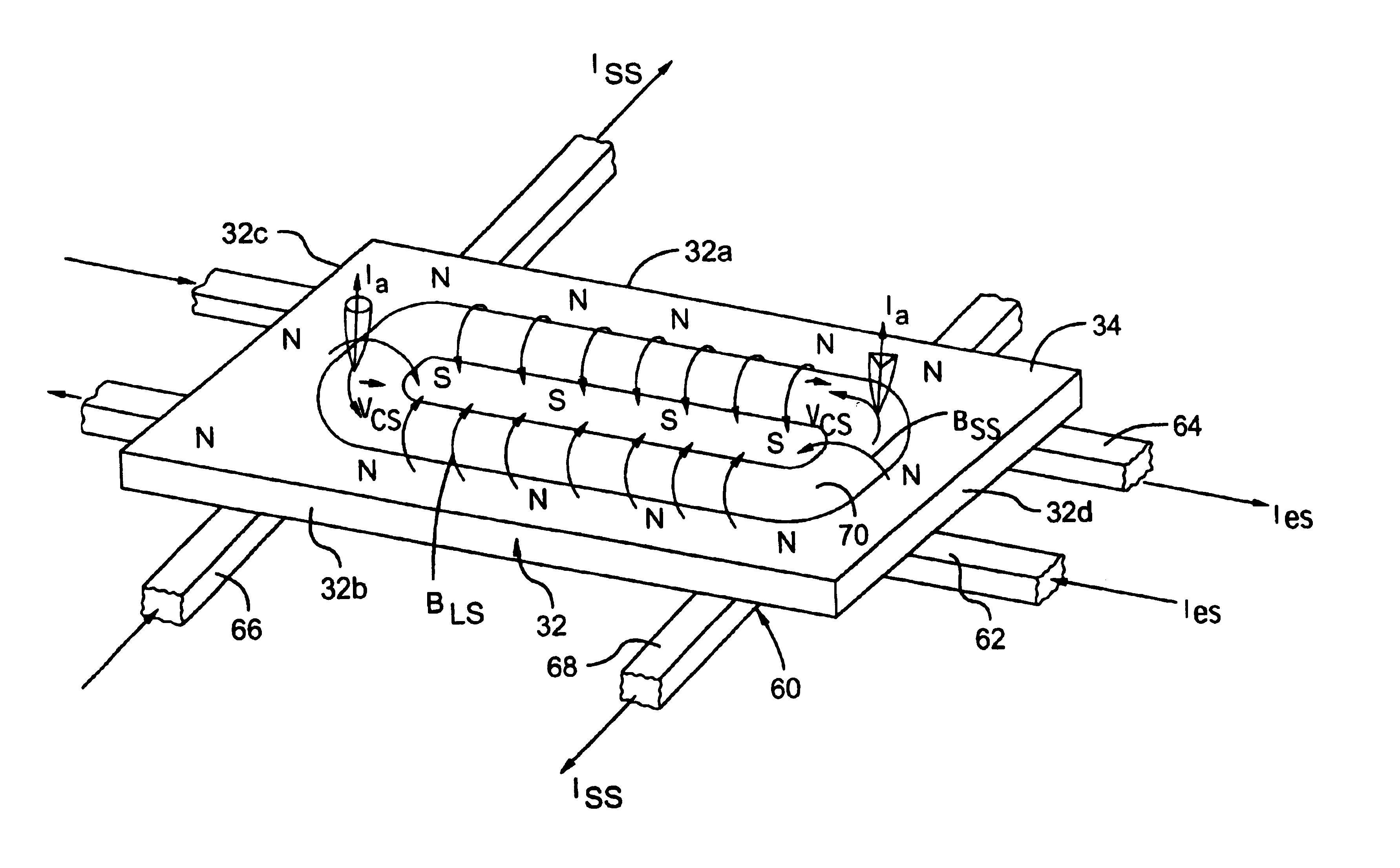
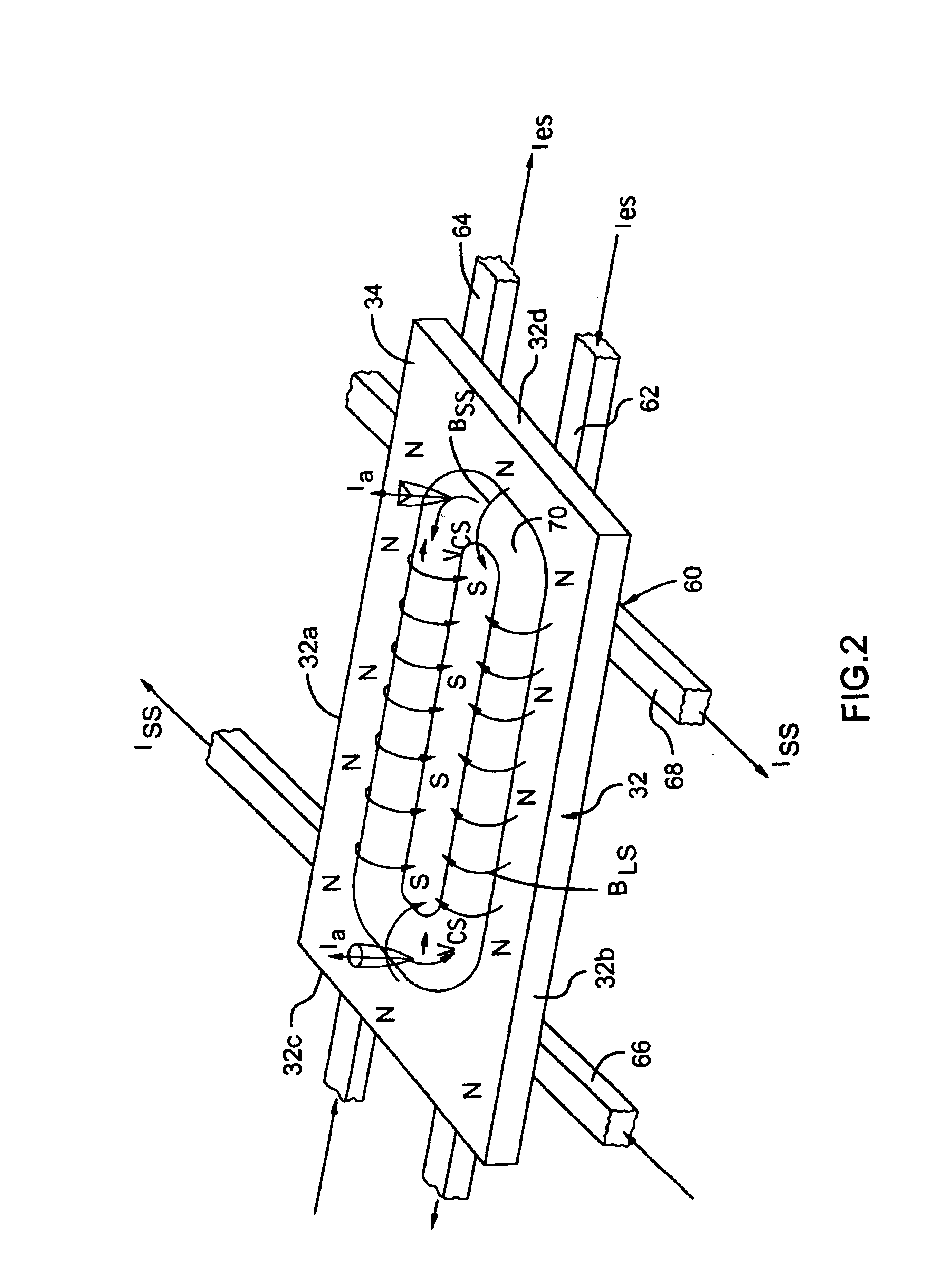
[0122]Deposition of a diamond-like coating (DLC) on set of knives such as scalpels, razors, knives for cutting papers using two rectangular arc sources mounted in the dual rectangular plasma guide chamber of FIG. 10 with deposition zone 500 mm height×300 mm width. The array of knives was installed on a rotating substrate platform facing the filtered arc source over the entire area of the deposition zone, with uniform rotation speed between about 10 to 20 rpm. A graphite rectangular plate evaporation target was attached to the cathode plate assembly. The current in the vertical steering conductors was set to 2000 amps, and the current in the horizontal steering conductors was set to 1300 amps. The arc current between the cathode and the primary (internal) anode plate was set to 300 amps. After igniting the arc with an impulse high voltage igniter, the arc spot began moving along an erosion corridor with an average speed ranging from 20 to 30 cm / s. About three to five cathodic arc spo...
example 2
[0125]Deposition of graphite coating on molybdenum glass for using as a substrate for flat panel display using rectangular molybdenum glass plates with dimensions 400 mm height×200 mm width×3 mm thick installed vertically on the rotating substrate platform. Each glass plate was attached to a metal plate-holder and a self bias of about 150 V was applied to the substrate platform using an RF generator with a 13.56 MHz frequency. The dual filtered cathodic arc source of FIG. 10 was provided with one aluminum target evaporation surface and one graphite target evaporation surface. The pressure during coating deposition was maintained at about 10−3 Pa. The temperature during deposition of the graphite coating was about 400° C., provided by an array of radiative electrical heaters.
[0126]In the first stage the arc was ignited on the aluminum target, providing an aluminum sublayer with thickness about 50 nm. In the second stage a graphite coating with thickness about 150 nm was deposited ove...
example 3
[0127]Deposition of TiAlN coatings on an array of hobs and end mills. The array of hobs and end mills was installed on substrate platform facing the filtered arc source exit over the entire area of the deposition zone, the substrate platform having a double (satellite) rotation with platform rotation speed 12 rpm. The dual rectangular filtered arc source of FIG. 10 was provided with an aluminum target evaporation surface mounted to one cathode and a titanium target evaporation surface mounted to the second cathode, for deposition of the TiAlN coating. The current for the titanium target was set at about 150 amps while current for the aluminum target was set at about 60 amps.
[0128]In the first stage the current of the auxiliary (external) anode was set at about 70 amps, providing a high density gaseous plasma immersed environment during both fast ion cleaning and coating deposition. The self bias potential of substrate platform provided by a RF 13.56 MHz generator was maintained at a...
PUM
| Property | Measurement | Unit |
|---|---|---|
| speed | aaaaa | aaaaa |
| pressure | aaaaa | aaaaa |
| self bias potential | aaaaa | aaaaa |
Abstract
Description
Claims
Application Information
 - R&D
- Intellectual Property
- Life Sciences
- Materials
- Tech Scout
- Unparalleled Data Quality
- Higher Quality Content
- 60% Fewer Hallucinations
Browse by: Latest US Patents, China's latest patents, Technical Efficacy Thesaurus, Application Domain, Technology Topic, Popular Technical Reports.
© 2025 PatSnap. All rights reserved.Legal|Privacy policy|Modern Slavery Act Transparency Statement|Sitemap|About US| Contact US: help@patsnap.com


