
NOx, Hg, and SO2 removal using ammonia
a technology of ammonia and nox, which is applied in the direction of emission prevention, separation processes, lighting and heating apparatus, etc., can solve the problems of not removing so2sub>2, serious safety concerns, and known negative health effects of byproducts on people, animals and plants
- Summary
- Abstract
- Description
- Claims
- Application Information
AI Technical Summary
Benefits of technology
Problems solved by technology
Method used
Image

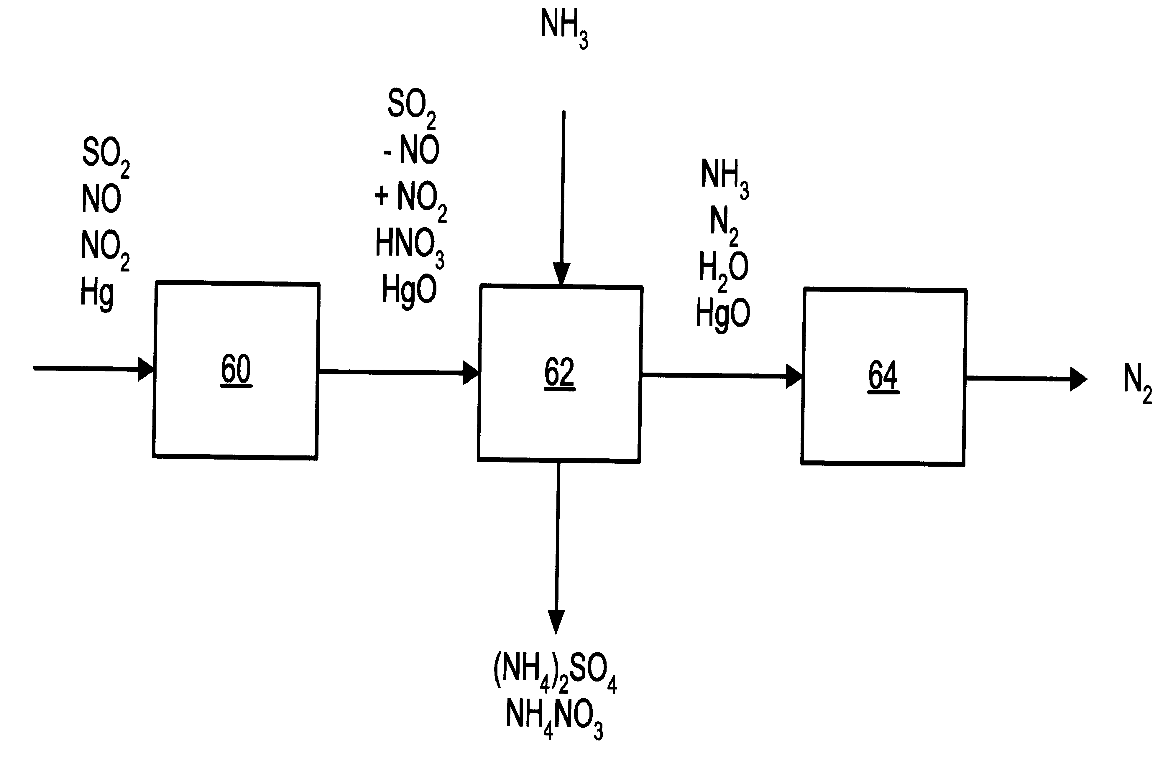
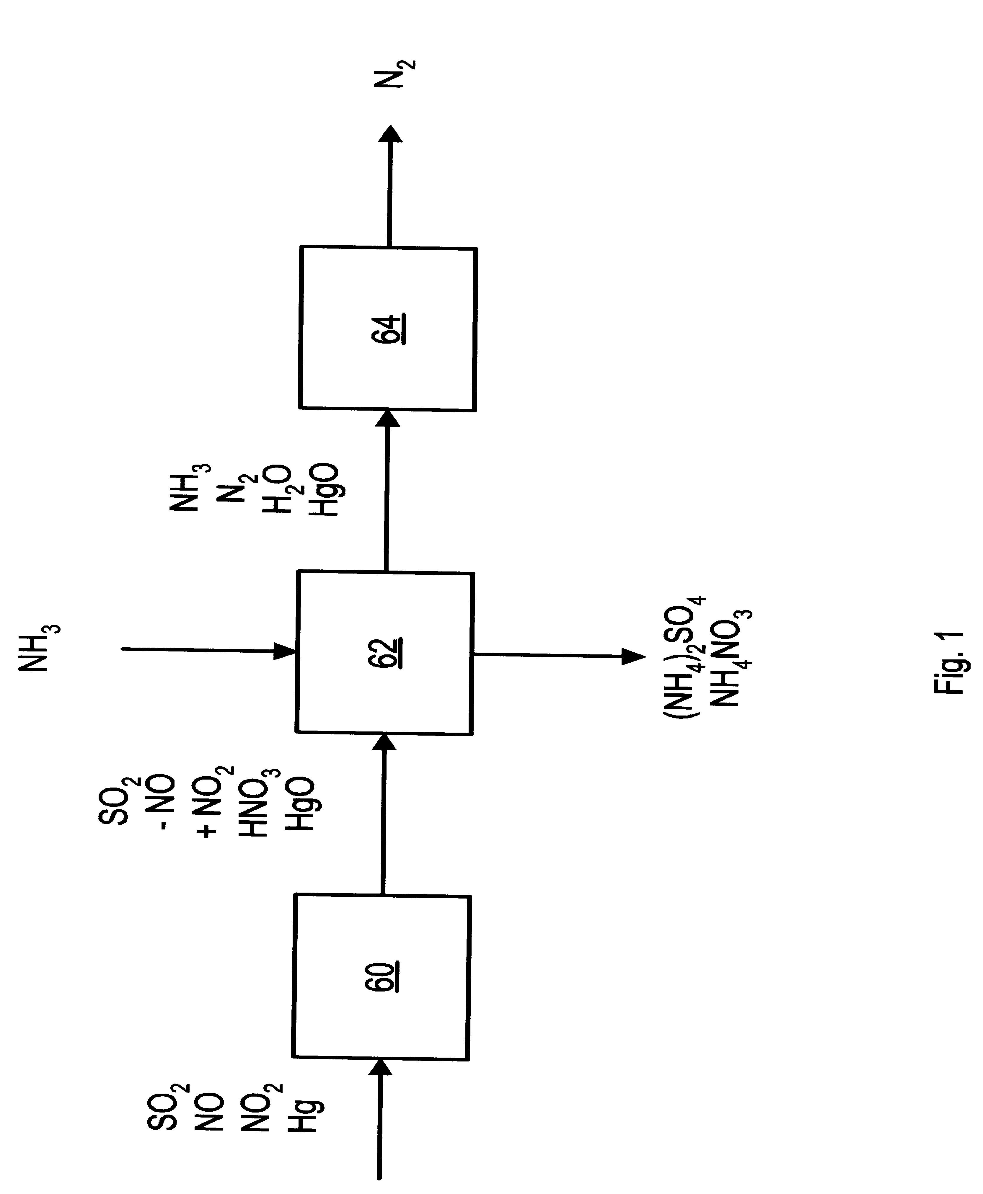
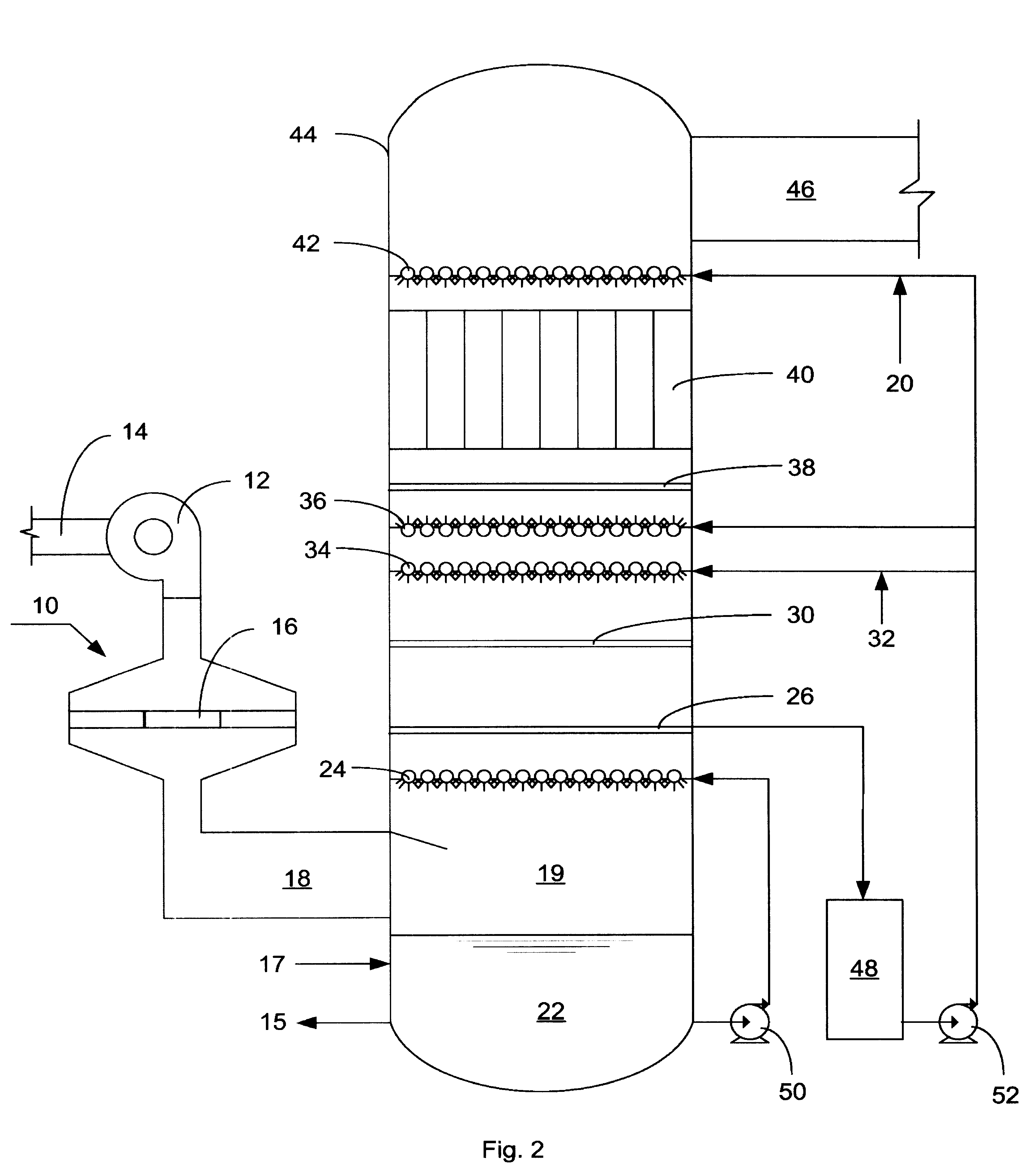
Examples
example 1
[0039]An absorption test was done for the scrubbing step of the process of the present invention, with a solution that was 1% w / w SO32− (“sulfite”), 6% w / w SO42− (“sulfate”), and 2.5% S2O32− (“thiosulfate”) in a packed column that was 18 inches high and 1.5 inches in diameter. The column was packed with ¼ inch glass RASCHIG rings. The simulated flue gas at the inlet of the column contained 13% v / v moisture, 6% v / v O2 and the simulated flue gas pollutants listed in the table. There was continuous addition of NH3 and (NH4)2S2O3 to maintain a pH of 6.8 and a thiosulfate concentration of 2.5% w / w. The residence time in the column was 1.8 sec with an L / G ratio of 25 gpm / kacfm.
[0040]The table shows the concentrations of NO, NO2, and SO2 at the inlet and outlet of the test system.
[0041]
TABLE 1Scrubbing Step AloneSystem InletSystem OutletNO (ppmv)204NO2 (ppmv)25036SO2 (ppmv)13702
example 2
[0042]An absorption test was done for the scrubbing step of the process of the present invention starting with water and a flue gas stream consisting of 13% v / v moisture, 17 ppmv NO, 267 ppmv NO2, 1360 ppmv SO2, 6% v / v O2 and balance N2. Ammonia and ammonium thiosulfate were added to maintain a pH of 6.8 and a thiosulfate concentration of 2.5%, and the concentrations of sulfite and sulfate in the system were allowed to build to steady state. The NOx removal rate was 80% w / w at concentrations of SO32−, SO42− and S2O32− of 0.7% w / w, 2.5% w / w, and 0.5% w / w respectively.
example 3
[0043]Tests were conducted in a laboratory test facility for the NO oxidizing, scrubbing, and aerosol removal steps of the process of the present invention. The equipment consisted of a simulated flue gas delivery system, a coaxial cylinder DBD reactor, a packed column scrubber and a tubular WESP. The following is an example of data obtained in the lab test facility.
[0044]Simulated flue gas was delivered to the DBD reactor at a flow rate of 14 scfm, a temperature of 290° F. and with the following composition: 6.2% v / v O2, 14.2% v / v CO2, 8.2% v / v H2O, 20 ppmv CO, 250 ppmv C2H4, 1740 ppmv SO2, and 259 ppmv NOx. Gas velocity through the discharge reactor was 50 ft / sec with discharge power level of 140 watts.
[0045]Gas from the discharge reactor entered a 4″ID packed column scrubber, packed with ½″INTALOX saddles to a depth of 4 feet. Liquid was introduced at the top of the scrubber at a flow rate of 0.33 gpm (L / G=20 gpm / kacfm). Aqueous ammonia was added to and effluent liquid removed fr...
PUM
| Property | Measurement | Unit |
|---|---|---|
| mole ratio | aaaaa | aaaaa |
| temperature | aaaaa | aaaaa |
| diameter | aaaaa | aaaaa |
Abstract
Description
Claims
Application Information