
Electrochromic organic polymer synthesis and devices utilizing electrochromic organic polymers

a technology of organic polymers and electrochromic organic polymers, applied in the field of electrochromic organic polymer synthesis and devices utilizing electrochromic organic polymers, can solve the problem of inconvenient use of liquid materials, and achieve the effect of high lateral resolution

Inactive Publication Date: 2006-02-21
UNIV OF WASHINGTON
View PDF18 Cites 6 Cited by
  • Summary
  • Abstract
  • Description
  • Claims
  • Application Information

AI Technical Summary

Benefits of technology

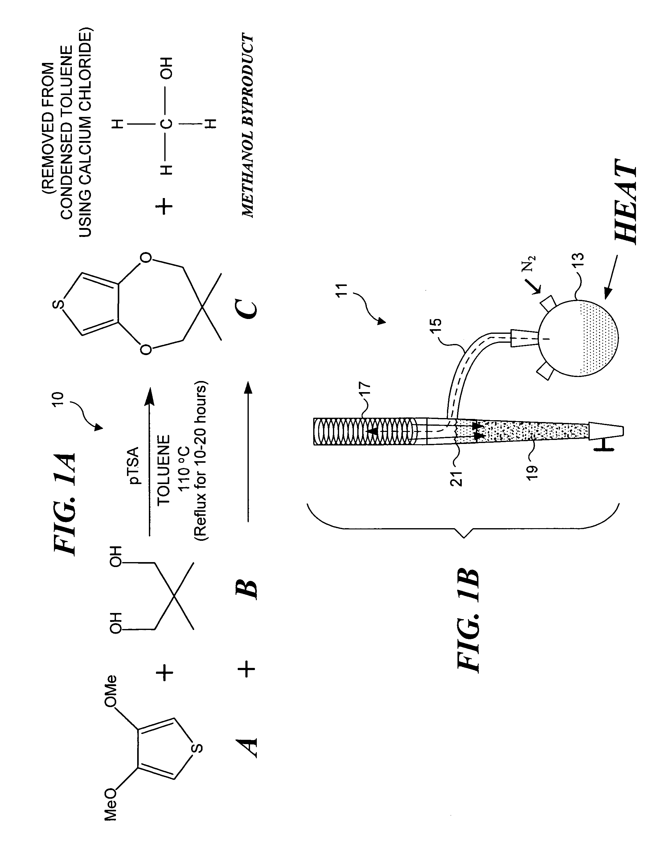
[0015]A methanol byproduct is produced during the synthesis, and that methanol byproduct significantly reduces the rate of the reaction. Preferably, the synthesis includes the step of removing the methanol byproduct by absorbing it with calcium chloride. This can be achieved by treating the condensed toluene vapors with calcium chloride before returning the condensed toluene vapors to the original boiling solution. This will remove the methanol byproduct from the condensed toluene vapors. As those of ordinary skill in the art will recognize, such a “salting out” process is sometimes employed in organic synthesis to remove undesirable reactants.
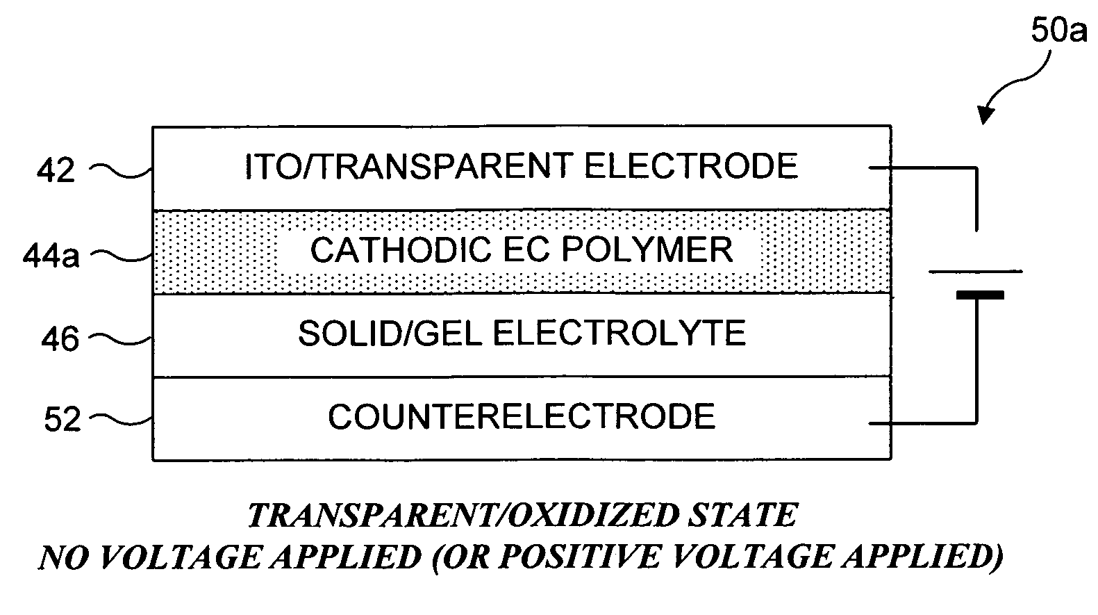
[0022]The embodiment of the EC device that has only a single EC polymer layer also includes a transparent electrode as a top layer. Again, indium tin oxide coated glass comprises a preferred transparent electrode. Examples of transparent electrodes are ITO and doped zinc oxide films deposited on transparent substrates, such as glass or plastics. After transparent electrode layer is the cathodic EC polymer layer, preferably PProDOT-Me2, followed by a solid electrolyte layer of the type described above. Adjacent to and following the solid electrolyte layer is a counter-electrode layer. A preferred counter-electrode layer includes a conductive coating applied to a transparent substrate (such as glass or plastic). Preferably, the conductive coating does not reduce transmittance through the counter-electrode layer by more than 25 percent. Preferred conductive coatings are gold and graphite, deposited in a pattern that substantially covers the substrate. A preferred pattern includes continuous lines, such as found in a grid. In the oxidized state, when no voltage negative (or a positive voltage) is applied, the PProDOT-Me2 polymer layers is substantially clear, with very little tint. When a negative voltage is applied, the counter-electrode enhances the speed with which the PProDOT-Me2 polymer layers undergoes a reduction and changes in color from nearly transparent to dark blue. The color change of the device is very rapid (about 0.5˜1 s) and repeatable (more than 10,000 times).
[0024]Still another application specific embodiment is directed to a DW for DNA chip and unknown molecules reading technology based on SPR imaging with high lateral resolution. Currently, DNA chip reading / writing technology requires expensive custom photomasks used in the photosynthesizing of oligonucleotides in DNA array fabrication. In this embodiment of the present invention, a DW including a plurality of individually addressable pixels arranged in a grid format is employed in the place of the conventional photomask. A voltage can be applied to each pixel individually, enabling selective masking to be achieved.

Problems solved by technology

For many applications, the use of a liquid material is inconvenient, and as a result, inorganic thin films and organic polymer films appear to be more industrially applicable.
While many inorganic materials have been used as EC materials, difficulties in processing and slow response time associated with many inorganic EC materials have created the need for different types of EC materials.

Method used


Image

  • Electrochromic organic polymer synthesis and devices utilizing electrochromic organic polymers
  • Electrochromic organic polymer synthesis and devices utilizing electrochromic organic polymers
  • Electrochromic organic polymer synthesis and devices utilizing electrochromic organic polymers

Examples


first embodiment

[0070]As noted above, highly conductive carbon (such as graphite) based counter-electrodes can also be employed. a highly conductive carbon based counter-electrode is shown in FIGS. 7A and 7B. Once again, a preferred substrate is a polished float glass cuvette plate, about 0.7 mm thick. An ITO coating 64 is applied on one side of the polished float glass cuvette plate, and a carbon coating 62 is then applied over the ITO coating. Preferably, the highly conductive carbon material is graphite (HITASOL GA.66M). The electrical conductivity of this highly conductive carbon material is known to be not less than 10−2 S / cm. Preferably, less than 25 percent of the glass substrate is covered with the carbon, in order to maintain high transmittance. While lithography and sputtering were employed for gold patterning on glass substrate as described above, screen printing was employed for forming a graphite pattern on a glass substrate for the highly conductive carbon-based counter-electrode. It ...

second embodiment

[0074]A sample device based on the single polymer / counter-electrode EC device described above was constructed using rectangular layers substantially 7 mm×50 mm. An ITO coated 7 mm×50 mm glass slide was prepared for the transparent electrode, and a layer of PProDOT-Me2 was deposited on the ITO coated surface. A glass wafer onto which a grid pattern of gold had been deposited was cut into 7 mm×50 mm plates. Similar 7 mm×50 mm plates of graphite deposited in a grid pattern were also prepared. A PMMA / LiClO4 gel electrolyte was uniformly placed between the cathodic EC polymer deposited on the ITO slide and the counter-electrode to form a layered device. Two devices were prepared, one with a gold counter-electrode, and one with a graphite counter-electrode layer. The graphite based counter-electrode differs from the gold based counter-electrode in that a layer of ITO was first placed on the glass substrate before the graphite was deposited, while no such layer was employed in the gold bas...


PUM

PropertyMeasurementUnit
sizeaaaaaaaaaa
transparentaaaaaaaaaa
temperatureaaaaaaaaaa

Abstract

Large contrast ratio and rapid switching laminated electrochromic (EC) polymer device includes transparent electrode, cathodic EC polymer, gel electrolyte, and counter-electrode. Preferably the cathodic EC polymer is a poly(3,4-propylenedioxythiophene) derivative, PProDOT-Me2. Counter-electrode is a conductive coating deposited on transparent substrate, with preferred coatings including gold and highly conductive carbon. Lithography and sputtering can be employed to pattern a gold layer, while screen printing can be employed to similarly pattern graphite. Empirical studies of preferred device indicate a color change of high contrast ratio of transmittance (>50% T) is rapidly (0.5–1s) obtained upon applied 2.5V, repeatable to at least 10,000 times, as estimated by electrochemistry. Dual layer EC devices including PProDOT-Me2 are also disclosed, as are methods for synthesizing preferred EC polymers. Preferred synthesis method for obtaining PProDOT-Me2 involves refluxing reagents in toluene in the presence of catalyst, while continually removing methanol byproduct from refluxing solution.

Description

RELATED APPLICATIONS[0001]This application is a divisional application of prior U. S. patent application Ser. No. 10 / 180,222, filed on Jun. 25, 2002, now U.S. Pat. No. 6,747,780 which itself is based on three prior copending provisional applications, including Ser. No. 60 / 300,675, filed on Jun. 25, 2001, Ser. No. 60 / 324,205, filed on Sep. 21, 2001, and Ser. No. 60 / 364,418, filed on Mar. 14, 2002, the benefits of the filing dates of which are hereby claimed under 35 U.S.C. § 120 and § 119(e).FIELD OF THE INVENTION[0002]The present invention generally relates to electrochromic (EC) materials that exhibit different colors as a function of an applied voltage, and more specifically, to apparatus utilizing specific organic polymer based EC materials, and methods of producing the specific organic polymer based EC materials.BACKGROUND OF THE INVENTION[0003]Electrochromic (EC) materials are a subset of the family of chromogenic materials, which includes photochromic materials, and thermochro...

Claims


Application Information

Patent Timeline
Patent Type & Authority Patents(United States)
IPC IPC(8): G02F1/153C08G61/12C09K9/02G02F1/15H01L51/00H01L51/30
CPCC09K9/02G02F1/15H01L51/0037G02F2001/1502G02F1/15165H10K85/1135
Inventor XU, CHUNYETAYA, MINORU
Owner UNIV OF WASHINGTON
Learn More