Near-field optical probe

a near-field optical and probe technology, applied in the field of near-field optical probes, can solve the problems of increasing the size of the microscope and its complexity, the minimum unit of analysis sample structure is limited to several hundred nanometers, and the optical microscope used for observing the optical characteristic distribution of a sample cannot realize structural observation with a resolving power, etc., to achieve efficient collection

Inactive Publication Date: 2006-03-21
SEIKO INSTR INC
View PDF4 Cites 110 Cited by
  • Summary
  • Abstract
  • Description
  • Claims
  • Application Information

AI Technical Summary

Benefits of technology

[0024]Accordingly, the light emitted from the light source can be efficiently collected at the microscopic aperture by the operation of the planar lens positioned above the microscopic aperture. Thus an optical probe is provided which can increase a near field to be generated but is compact in structure.
[0042]Accordingly, the scattering light emitted by the microscopic aperture can be efficiently collected at the light detector by the operation of the planar lens or the light collecting layer positioned above the microscopic aperture. Thus an optical probe can be provided to which can increase in detected scattering light but is compact in structure.

Problems solved by technology

The typical optical microscope used for observing an optical characteristic distribution of a sample cannot realize structural observation with a resolving power of less than a half of its wavelength due to a diffraction limit of visible light used for illuminating the sample, i.e. propagated light.
Consequently, in the optical microscope the minimum unit for analyzing sample structure is limited to several hundreds of nanometers.
On the other hand, in the electron microscope capable of sample surface observation with higher resolving power, because an electron beam with high energy is irradiated on a sample surface to be observed, there has been a trend of damaging a sample or increasing the size of the microscope and its complexity.
However, the optical fiber probe explained above has a sharpened tip, and accordingly is not sufficient in mechanical strength and not suited for mass production and arraying.
Also, in the cantilever type optical probe explained above, because an optical fiber is inserted to the aperture portion to achieve reception of the scattered light from the optical waveguide layer or introduction of the propagated light to the optical waveguide layer, a sufficient amount of light could not be propagated without loss between the optical waveguide layer and the optical fiber.
Furthermore, where a ball lens is provided in the aperture portion, the ball lens cannot necessarily adjust a focal point to a light inlet / outlet surface of the optical fiber or an optical waveguide layer tip portion, thus making it impossible to effect optimal light collection.
Also, in the cantilever type optical waveguide probe explained above, there is a similar problem between the propagation light to the optical waveguide and the optical detector or the propagation light from a light source, to the case of using a cantilever type optical probe as stated above.
The cantilever type optical probe and the cantilever type optical waveguide probe are both difficult to realize particularly arraying in two dimensional arrangement.
High speed scan is difficult over a recording medium.

Method used


Image

  • Near-field optical probe
  • Near-field optical probe
  • Near-field optical probe

Examples


embodiment 1

[Embodiment 1]

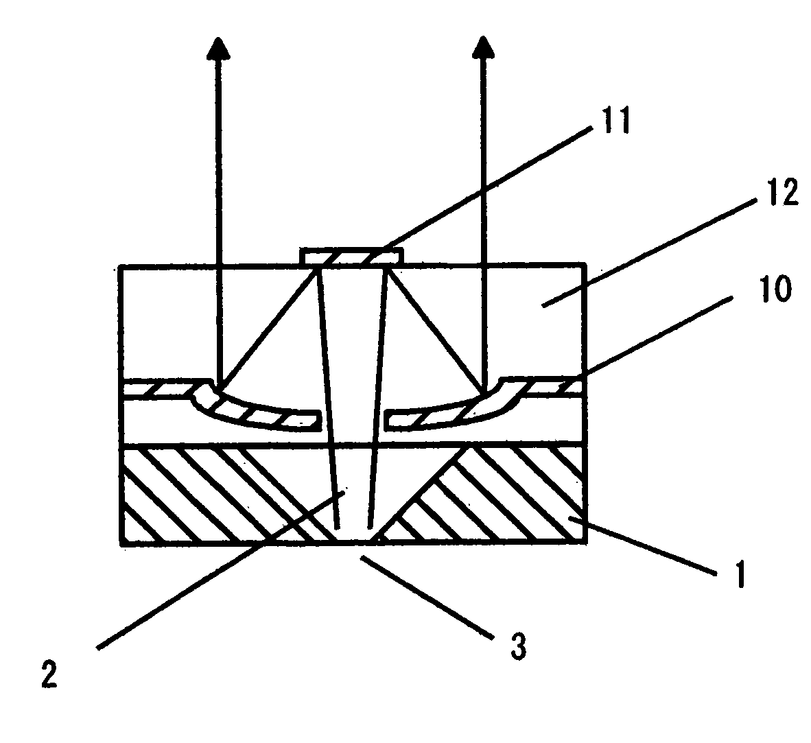
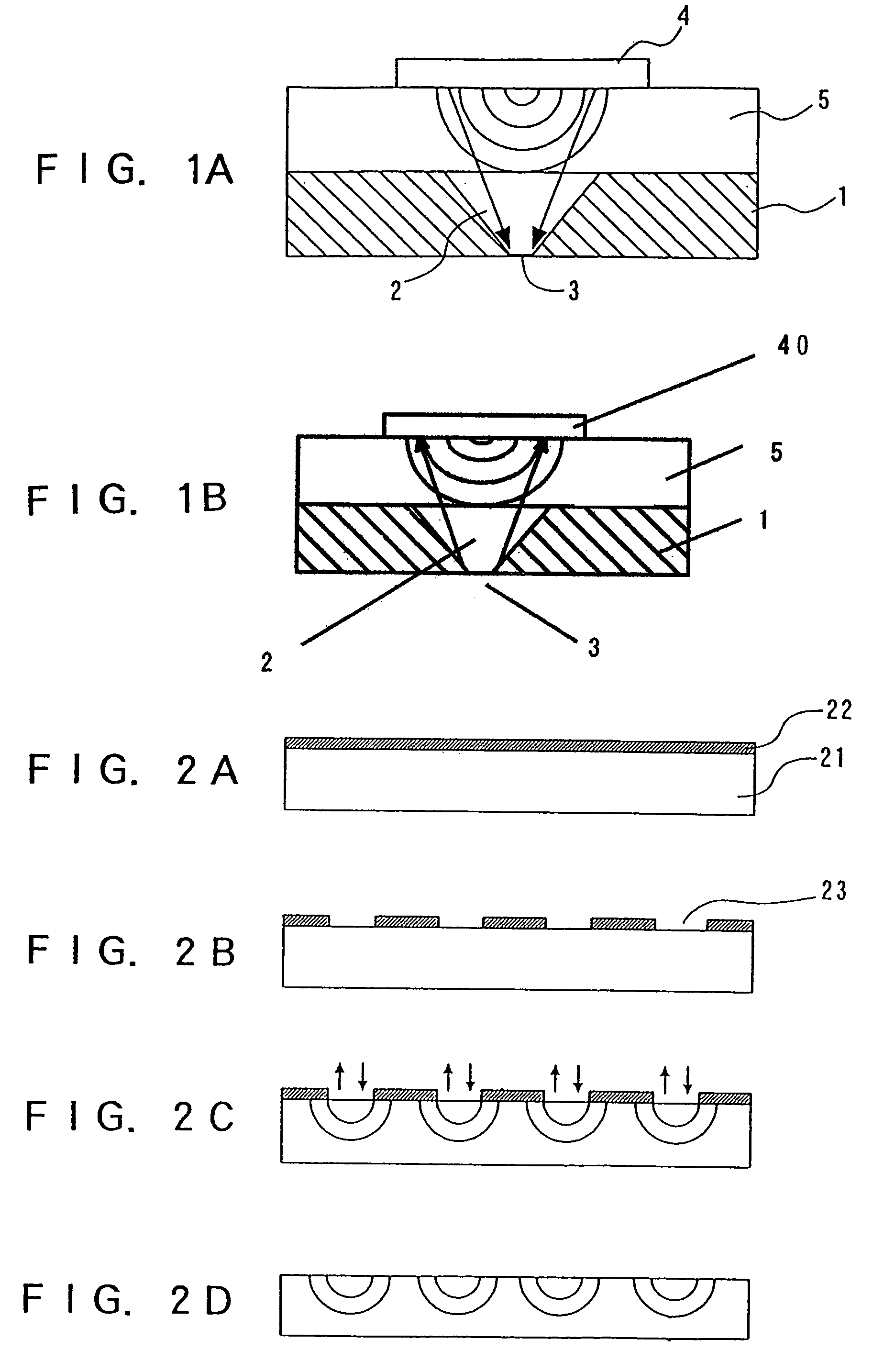
[0054]FIG. 1A shows a sectional view of one part of a near-field optical probe according to Embodiment 1.

[0055]In FIG. 1A, a silicon substrate 1 with an aperture 3 has a planar microlens 5 wherein a surface emitting laser 4 is further provided on the planar microlens 5.

[0056]The silicon substrate 1 is formed with a taper portion 2 in a manner penetrating through it, to have a microscopic aperture 3. The aperture 3 has a diameter, for example, of 50 nanometers so that a near field can be generated by the light introduced through the taper portion 2. The taper portion 2 is formed by microlithography using conventional photolithography or silicon anisotropic etching. For example, a silicon substrate 1 having a (100) plane at both surfaces is formed by thermal oxide films or Au / Cr metal films as masks for anisotropic etching to be subsequently conducted. The mask on one of the surfaces is partially removed to form an aperture window, thereby exposing the (100) plane. Subse...

embodiment 2

[Embodiment 2]

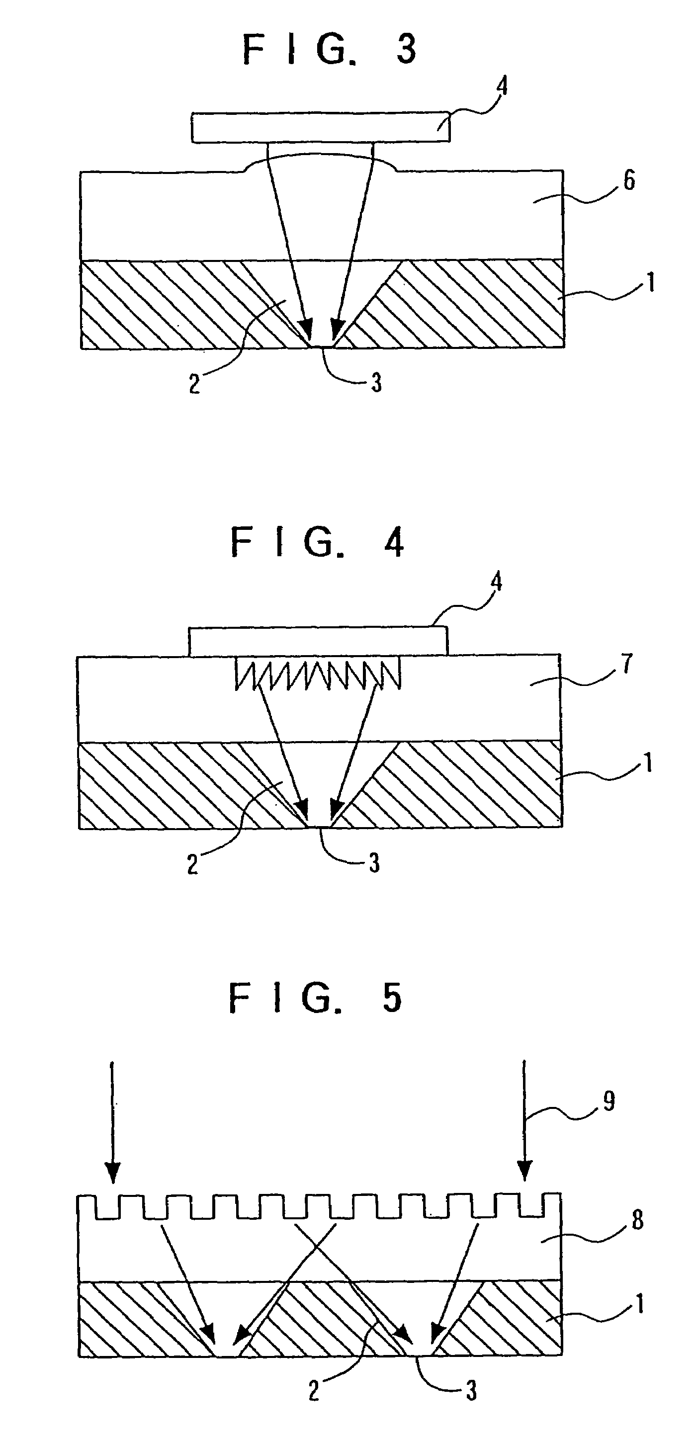
[0072]FIG. 3 shows a sectional view of one part of a head for an optical memory according to Embodiment 2.

[0073]In FIG. 3, a microlens substrate 6 is arranged in place of the planar microlens 5 of FIG. 1 explained in Embodiment 1.

[0074]In the microlens substrate 6, in a selective ion exchange method similar to that explained in Embodiment 1, ions large in radius are diffused into the glass substrate and are selected to cause a swell at a circular aperture portion due to a difference in diameter of ions to be exchanged. Accordingly, a lens is made in a usual lens shape, different from the gradient refractive index created as a result of selective ion exchange in Embodiment 1. Due to this swell, the microlens substrate 6 is not flat in its surface so that surface emitting laser 4 cannot be arrange directly thereon. Consequently, there is a necessity to provide a distance between the microlens substrate 6 and the surface emitting laser 4. A not-shown spacer is used in fix...

embodiment 3

[Embodiment 3]

[0080]FIG. 4 shows a sectional view of one part of a near-field optical probe according to Embodiment 3.

[0081]In FIG. 4, a Fresnel zone plate 7 is arranged in place of the planar microlens 5 of FIG. 1 explained in Embodiment 1. The Fresnel zone plate 7 is used to create diffraction light by a fine pattern on a glass substrate to cause a lens effect. It is possible to collect the coherent light given from the surface emitting laser 4 in the aperture 3 without aberration. The fine processing for the Fresnel zone plate 7 can use various method including electron beam processing, laser interference method, dry etching method and fine machining. However, if a master is made, mass production is possible by stamping or the like.

[0082]The provision of a Fresnel zone plate between the surface emitting laser as a light source and the aperture can increase the intensity of a near field to be generated or detected in the aperture.

[0083]Incidentally, a holographic lens 8 amy be use...


PUM

PropertyMeasurementUnit
diameteraaaaaaaaaa
refractive indexaaaaaaaaaa

Abstract

A near-field optical probe has a flat support member having opposed flat surfaces, and a tapered through-hole extends through the support member and terminates at one of the flat surfaces in a narrow aperture. A light collecting layer having a plurality of reflective surfaces is disposed on the support member for collecting and focusing light passing through the narrow aperture. An optical detector disposed above the light collecting layer detects light passing through the light collecting layer.

Description

CROSS-REFERENCE TO RELATED APPLICATIONS[0001]The present application is a division of application Ser. No. 10 / 339,074 filed on Jan. 9, 2003, now U.S. Pat. No. 6,881,947, which is a division of application Ser. No. 09 / 402,382 filed Jun. 26, 2000 and now U.S. Pat. No. 6,528,780, and priority thereto for common subject matter is hereby claimed.TECHNICAL FIELD[0002]The present invention relates to a near-field optical probe capable of reproducing and recording information with high density utilizing a near field, and more particularly to near-field optical probes that are arranged in an array.BACKGROUND OF THE INVENTION[0003]The typical optical microscope used for observing an optical characteristic distribution of a sample cannot realize structural observation with a resolving power of less than a half of its wavelength due to a diffraction limit of visible light used for illuminating the sample, i.e. propagated light. Consequently, in the optical microscope the minimum unit for analyz...

Claims


Application Information

Patent Timeline
Patent Type & Authority Patents(United States)
IPC IPC(8): H01J3/14G01B11/30G01N37/00G01Q20/02G01Q60/18G01Q60/22G01Q70/02G01Q70/06G01Q70/16G11B7/135G11B7/22
CPCB82Y10/00B82Y20/00B82Y35/00G01Q60/22G01Q70/06G01Q70/16G11B7/1353G11B7/1362G11B7/1374G11B7/1387G11B7/128G11B2007/13727G11B7/22Y10S977/862
Inventor MITSUOKA, YASUYUKICHIBA, NORIOKASAMA, NOBUYUKINIWA, TAKASHINAKAJIMA, KUNIO
Owner SEIKO INSTR INC
Why Eureka
Try Eureka