Cemented carbide and cutting tool

a cutting tool and cemented carbide technology, applied in the field of cemented carbide and cutting tools, can solve the problems of poor cutting surface state, inability to perform good cutting, rapid progress of cutting tools, etc., and achieve excellent cutting, high temperature strength, and high cutting efficiency.

Inactive Publication Date: 2006-03-28
KYOCERA CORP
View PDF17 Cites 13 Cited by
  • Summary
  • Abstract
  • Description
  • Claims
  • Application Information

AI Technical Summary

Benefits of technology

[0018]A main object of this invention is to provide a cemented carbide which has high hardness and a toughness.
[0020]Other object of this invention is to provide a surface coating cemented carbide which is excellent in oxidation resistance while having high hardness and high toughness, and can improve high fracture resistance and high wear resistance in severe environment as exposed to high temperature by continuation operation etc.
[0031]Inventors found out the following facts. That is, in a cemented carbide containing a WC phase and a binder phase of a iron-group metal, at least two solid solution phases selected from carbides, nitrides, and carbonitrides of metals of the groups 4a, 5a and 6a in the Periodic Table and containing Zr and Nb at least, are precitipated. Further, the cemented carbide has the 1st phase having a peak in 2θ=40.00–41.99° and the 2nd phase having a peak in 2θ=38.00–39.99° in the X-ray diffraction of the cemented carbide. As a result, hardness and high temperature strength of the cemented carbide can be raised.
[0032]A cutting tool obtained by using the cemented carbide of this invention has wear resistance, plastic deformation resistance, and fracture resistance which were excellent in cutting of hardly machinable material, such as stainless steel, and high efficiency cutting is attained.
[0034]Here, it is desirable that the ratio (p2 / p1) of strength (p1) of the 1st peak, and strength (p2) of the 2nd peak is 0.1–2. The content ratio (Zr / Zr+Nb) of Zr and Nb may be 0.5–0.7. The cemented carbide having the surface region of p2>0 and p1=0 shows toughness and the excellent fracture resistance.
[0055]Inventors found out the facts that, when a 1st surface region and a 2nd surface region provided inside of the 1st surface region as mentioned below are provided to the surface of a cemented carbide, oxidation resistance of the cemented carbide forming a coating can be raised, in addition to raising toughness of the surface of the cemented carbide and raising fracture resistance of a hard coating. Accordingly, in case of operating continuously or intermittently for a long time, thereby exposing to high temperature for a long time, a surface coating cemented carbide has excellent fracture resistance and wear resistance

Problems solved by technology

However, since such a cutting difficult material has characters such as generation of work hardening, high affinity with tool material and low thermal conductivity, many problems has generated in the field of cutting.
When cutting of the hardly machinable material, such as a stainless steel, is carried out with a cutting tool made from K-grade cemented carbide which is composed of WC—Co system cemented carbide specified to JIS B 4053 (1996) which is comparatively few amounts of Co, or a cutting tool made from P-grade cemented carbide which has B1 type (cubic type) solid solution of single composition, wear of a cutting tool progresses rapidly, or a fracture whose welding is considered to be a cause is generated, a processing surface state of cutting material gets worse.
As a result, it becomes a tool life for a short time, and good cutting can not be performed.
Moreover, a damage to primary notch parts with a cutting force received from a processing surface which carried out work hardening is intense, and it results in a tool life immediately, and comes to acquire good cutting characteristics.
As a result, welding or agglutination of the workpiece to the cutting tool surface is carried out, and action parts (piece edge etc.) are unusually worn out, or a cutting force is increased, whereby it becomes easy to generate damage on a cutting tool surface.
Moreover, there was a problem that a finished-surface coarseness of a surface to be cut deteriorates by an unevenness of a welding thing or an agglutination thing.
An iron (Fe) and a chromium (Cr) in are contained in a primary raw material as an unescapable impurity, or are contained in the cemented carbide during a manufacturing process, and cannot be perfectly removed on industry.
Moreover, a content of iron (Fe) and chromium (Cr) which are contained during a manufacturing process is uncontrollable, since it is changeable in connection with change of process and surface states of a grinder or the like.
Consequently, the hard coat is exfoliated and destroyed, or a life falls in using as cutting tool or slide member.
However, it is known that when surfaces of these cemented carbides are oxidized and deteriorated with a heat at the time of cutting and oxygen in environment, its hardness and toughness fall.

Method used


Image

  • Cemented carbide and cutting tool
  • Cemented carbide and cutting tool
  • Cemented carbide and cutting tool

Examples


example

Example I

1st Cemented Carbide

[0186]Tungsten-carbide (WC) powder of 8.0 μm of mean particle diameters shown in Table 1, the metal cobalt (Co) powder of 1.2 μm of mean particle diameters and the compound powder of 2.0 μm of mean particle diameters shown in Table 1 were added and mixed by the ratio shown in Table 1.

[0187]After molding the mixture in cutting tool shape (SDK42, CNMG43) by the press forming, cemented carbide was produced by raising a temperature at the velocity of 10° C. / min. from a temperature lower 500° C. or more than a sintering temperature, followed by sintering at 1500° C. for 1 hour.

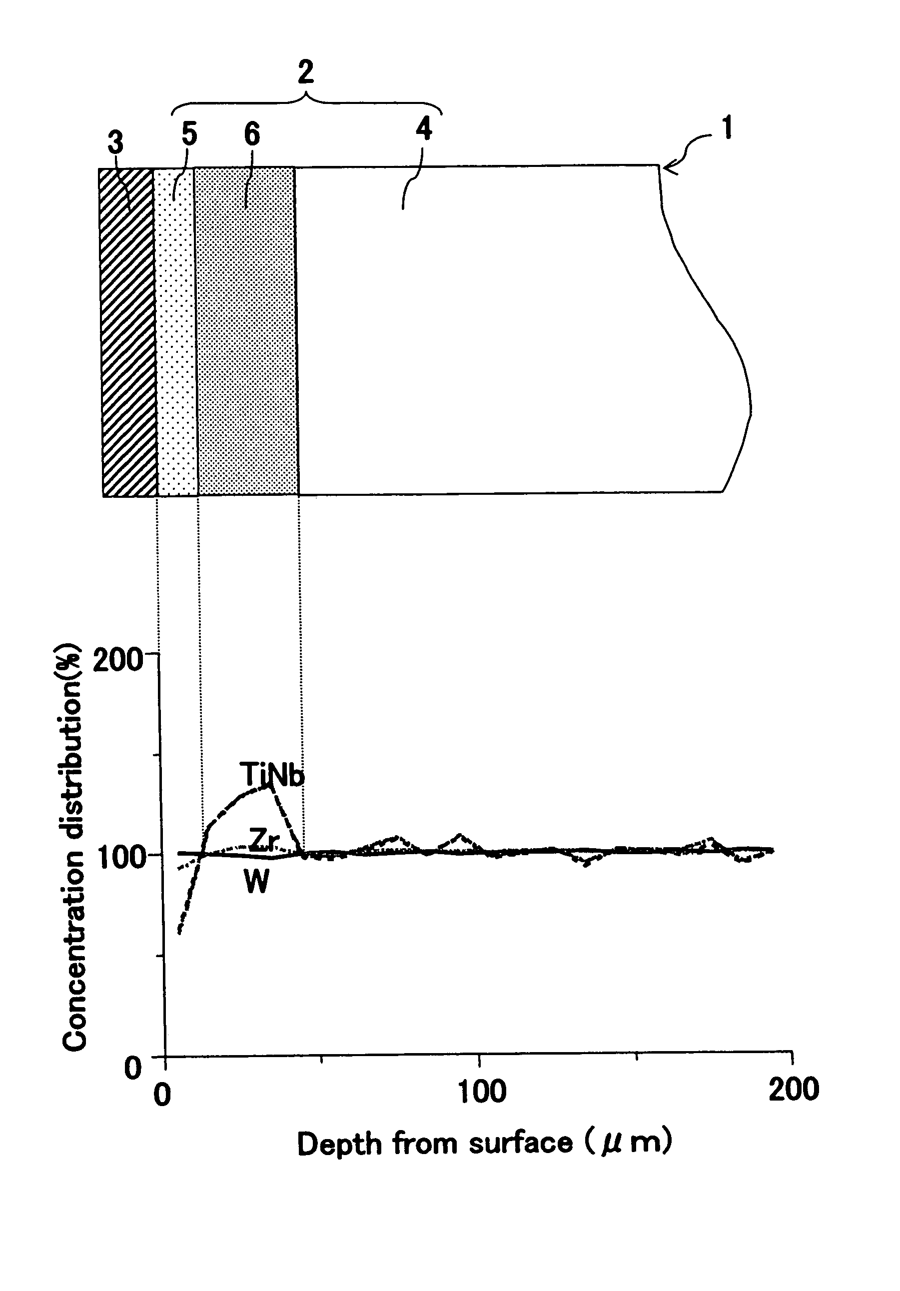
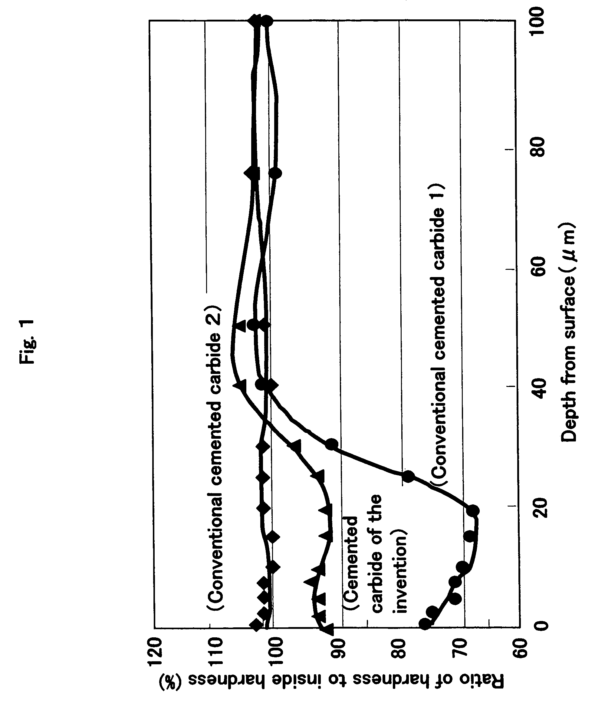
[0188]In the cut side in the direction of oblique section including the arbitrary surface, hardness was measured toward the inside in the portion which is equivalent to each depth from the surface.

[0189]The measurement was performed by using the micro Vickers equipment (MVK-G3) made from Akashi Corporation, on conditions of 200 g of loads and 10 seconds of retention time. The hardness i...

example ii

2nd Cemented Carbide

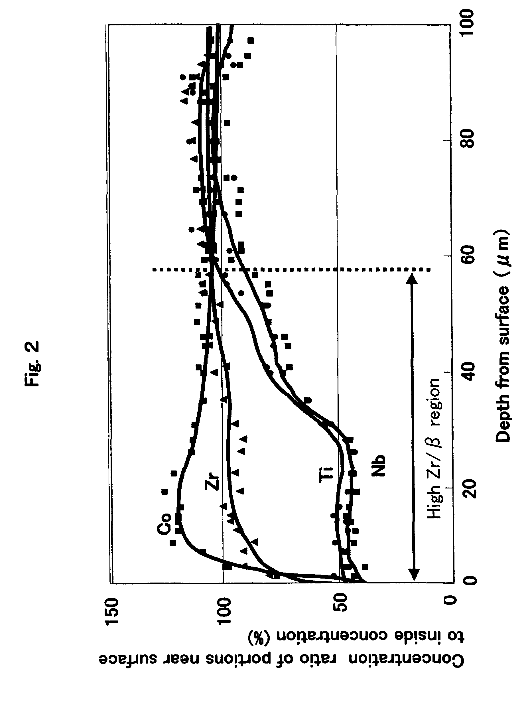
[0216]Tungsten-carbide (WC) powder of a mean particle diameter shown in Table 3, the metal cobalt (Co) powder; of 1.2 μm of mean particle diameters and the compound powder of 2.0 μm of mean particle diameters shown in Table 3 were added and mixed by the ratio shown in Table 3. After molding the mixture in cutting tool shape (SDK42) by the press forming, cemented carbide was produced by raising a temperature at the velocity of 10° C. / min. from a temperature lower 500° C. or more than a sintering temperature, followed by sintering at 1500° C. for 1 hour.

[0217]About three arbitrary sections of the obtained cemented carbide, X-ray diffraction analysis was performed using Kα1 ray of Cu vessel at angle of diffraction 2θ=30–80°, mesurement time 0.5 sec, voltage 40 kV, and current 40 mA, with the X-ray-diffraction-analysis equipment (RINT1100) made by Rigaku Denki company. Furthermore, in order to remove the mutual error of all data, the peak which WC (100) side in each ...

example iii

3rd Cemented Carbide

[0228]Tungsten-carbide (WC) powder whose mean particle diameter is 9 μm containing Iron (Fe) and chromium (Cr) in the amount shown in Table 5, metal cobalt (Co) powder and compound powder were weighed at the ratio shown in Table 5, and these powders were introduced in a attriter mill which has an inner wall, a media, and a stirring arm which consist of cemented carbide of 99.99% or more of purity.

[0229]After carrying out wet grinding for 18 hours by adding 2-propanol and granulating by spray dry, it molded in cutting tool shape (SDK1203) by the press forming.

[0230]Next, the obtained green body was setted to the vacuum sintering furnace, predetermined-time retention was carried out with the 1st sintering temperature shown in Table 5 which carried out a temperature up at the velocity for 12° C. / min., the temperature was lowered to the 2nd sintering temperature at the temperature fall velocity shown in Table 5, predetermined-time retention was carried out with this ...


PUM

PropertyMeasurementUnit
total thicknessaaaaaaaaaa
thicknessaaaaaaaaaa
thicknessaaaaaaaaaa

Abstract

There is provided a cemented carbide comprising a hard phase component which comprises a tungsten carbide (WC) and at least one selected from carbides, nitrides and carbonitrides of metals of the groups 4a, 5a and 6a in the periodic table; and a binder phase component comprising at least one of iron-group metals, wherein the surface region of the cemented carbide has 90–98% of the minimum hardness as compared with internal hardness, thereby having high hardness and toughness which is suitable to using as a cutting tool.

Description

[0001]This is a divisional of application Ser. No. 10 / 256,275 filed Sep. 26, 2002, now U.S. Pat. No. 6,797,369 which application is hereby incorporated by reference in its entirety.FIELD OF THE INVENTION[0002]This invention relates to a cemented carbide and a cutting tool using a cemented carbide, and more particularly to a cemented carbide and a cutting tool having a hardness and a toughness suitable for cutting of a hardly machinable material such as a stainless steel, besides a steel and cast iron, such as a carbon steel and an alloy steel, and further excelled in a wear resistance.BACKGROUND OF THE INVENTION[0003]As a cemented carbide widely used for cutting of metal, a WC—Co alloy which is composed of a hard phase wherein tungsten carbide WC is a main component, and a binder phase of iron-group metals, such as cobalt), or an alloy wherein a carbide, a nitride, a carbonitride, etc. of metals of group 4a, 5a, or 6a in the periodic-table were further added to the WC—Co is known.[0...

Claims


Application Information

Patent Timeline
Patent Type & Authority Patents(United States)
IPC IPC(8): B32B9/00B24D3/06B24D5/12C22C29/02C22C29/08
CPCB24D3/06B24D5/12C22C29/02C22C29/08B22F2005/001Y10T428/30B22F2999/00B22F2998/10Y10T428/265Y10T428/24942Y10T428/252Y10T428/24983B22F9/04B22F3/1017B22F2207/01C22C29/06
Inventor USAMI, KEIJISHIBATA, DAISUKEOHATA, HIROSHI
Owner KYOCERA CORP
Why Eureka
Try Eureka