Inductively coupled plasma generator having low aspect ratio

a plasma generator and inductive coupling technology, which is applied in the direction of plasma technique, coating, electric discharge lamps, etc., can solve the problems of difficult oxide etching application, increase in the residence time of gas in the chamber, and complicated operation, so as to achieve accurate fabrication of large-diameter semiconductor wafers, reduce chamber volume, and high selectivity

Inactive Publication Date: 2006-08-08
SEMES CO LTD
View PDF13 Cites 13 Cited by
  • Summary
  • Abstract
  • Description
  • Claims
  • Application Information

AI Technical Summary

Benefits of technology

[0012]To overcome several problems of the prior art, it is an object of the present invention to provide an inductively coupled plasma generator having a lower aspect ratio, which can reduce an electron temperature to be suitable for etching an oxide film, ensure high selectivity by reducing a volume of a chamber, and can accurately fabricate a large-diameter semiconductor wafer by establishing rotation symmetry of a plasma density profile and uniformly maintaining plasma densities at the peripheral and central portions of the chamber.
[0013]To achieve the object of the present invention, there is provided an inductively coupled plasma generator comprising a chamber having a gas inlet through which a reaction gas is supplied, a vacuum pump for maintaining the inside of the chamber vacuum and a gas outlet for exhausting the reaction gas after completion of the reaction, a chuck for mounting a target material to be processed inside the chamber, and an antenna to which high-frequency power is applied, the antenna provided at the upper and lateral portions of the chamber, wherein the antenna has parallel antenna elements in which a discharge of a high frequency in the range of 50 MHz˜100 MHz can be allowed and impedance is low to ensure a low electron temperature, the antenna is disposed such that a powered end of each of the antenna elements and a ground end of each of the antenna elements opposite to the powered end are symmetrical in view of the center of an imaginary circle formed by the antenna to establish rotation symmetry of plasma density profiles, the antenna elements are twisted in a helical manner, and the powered end of each of the antenna elements is positioned to be far from the chamber and the ground end of each of the antenna elements is positioned to be close to the chamber, thereby compensating for a drop in the plasma density due to ion loss occurring at the powered end.
[0014]In the present invention, the respective antenna elements constituting the parallel antenna are twisted in a helical manner to be positioned on the same radius, the powered end of each antenna element is positioned to be far from the chamber, that is, at a relatively upper or outer portion of the chamber, and the ground end of each antenna element is positioned to be close to the chamber, that is, at a relatively lower or inner portion of the chamber, so that a high voltage is applied to the powered end, thereby minimizing a reduction in plasma density due to ion loss of the powered end. Also, a plasma density reduction due to ion loss occurring at the powered end, and a plasma density reduction due to a non-inductive electric field at the disconnected portion of the powered end and the ground end of an antenna, can be compensated for because the central portions of the other antenna elements having the same radium and twisted with each other in a double-helical manner, that is, a portion at which plasma density is relatively higher than at the powered end P, overlap at the same location, thereby ensuring rotation symmetry of a plasma density profile.

Problems solved by technology

However, this approach is complicated to carry out and is difficult to be applied to oxide etching.
In other words, since oxide etching requires high selectivity in view of processing conditions, a conventional inductively coupled plasma generator in which uniformity of plasma is controlled by a diffusion method, uses a relatively bulky chamber, resulting in an increase in the residence time of gas in the chamber.
As described above, there are several disadvantages in using the conventional inductively coupled plasma generator.
In this case, it is difficult to adjust distribution of inductive electric field, causing loss in ions and electrons on the inner wall of the chamber.
Thus, plasma density is unavoidably increased at the center of the chamber and reduced in the neighborhood of the inner wall of the chamber.
Thus, it is quite difficult to maintain plasma density at a uniform level.
Also, since the respective inductive coils of the antenna are connected to one another in series, a voltage drop due to the antenna is increased and the antenna is greatly affected by capacitive coupling with plasma.
Thus, power efficiency is lowered and it is difficult to maintain uniformity of plasma density.
Next, in the antenna constructed of three separate electrodes, plasma density is high at a location close to the respective separate electrodes connected to three different high-frequency power sources, and plasma density is low at the center of the chamber, making it difficult to maintain uniformity of plasma.
In particular, it is quite difficult to process samples over a wide area.
Also, since independently operating power sources are used, the cost increases.
In such a manner, plasma density becomes asymmetrical with respect to the rotating direction because a relatively high voltage is applied to the powered end of the antenna, causing ion loss, resulting in a drop in plasma density.
Accordingly, uniform processing of a target material to be processed is difficult to achieve.

Method used


Image

  • Inductively coupled plasma generator having low aspect ratio
  • Inductively coupled plasma generator having low aspect ratio
  • Inductively coupled plasma generator having low aspect ratio

Examples


Embodiment Construction

[0032]Non-limiting embodiments of the present invention will now be described in detail with reference to the accompanying drawings.

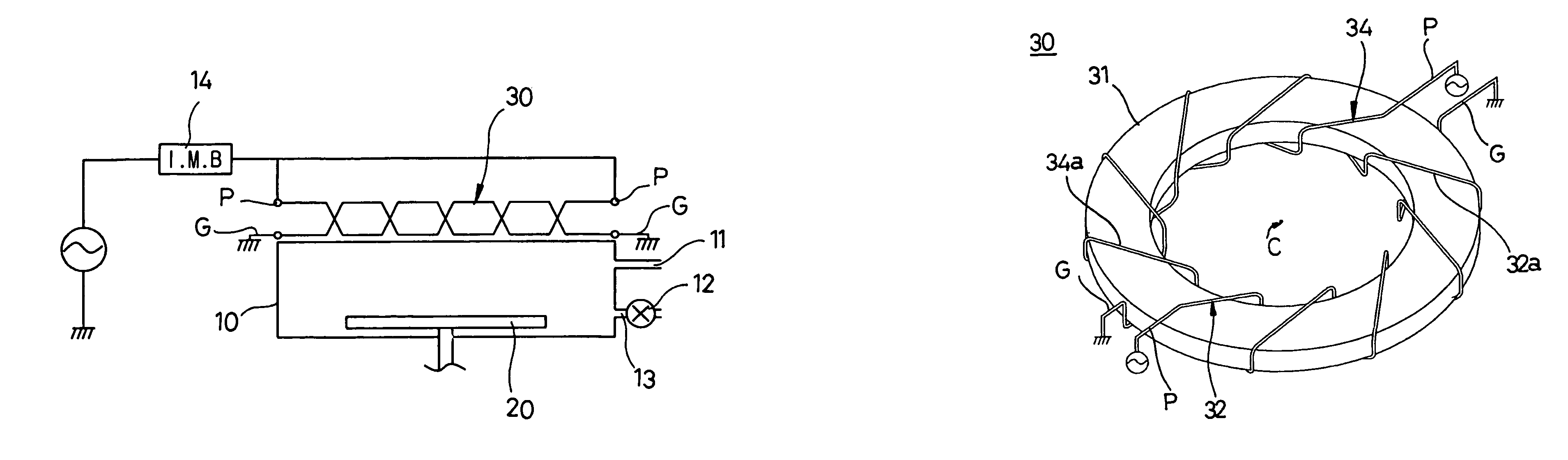
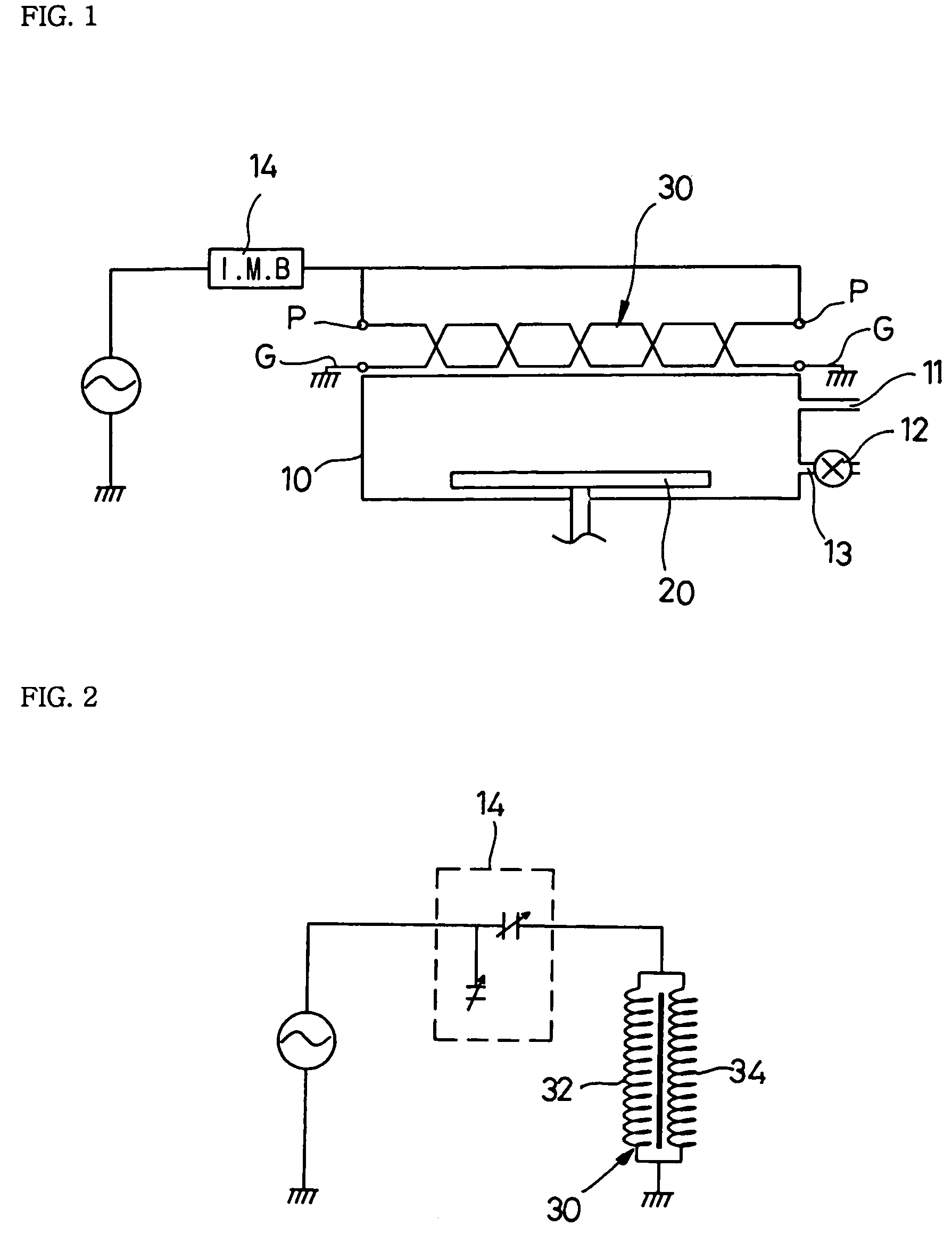
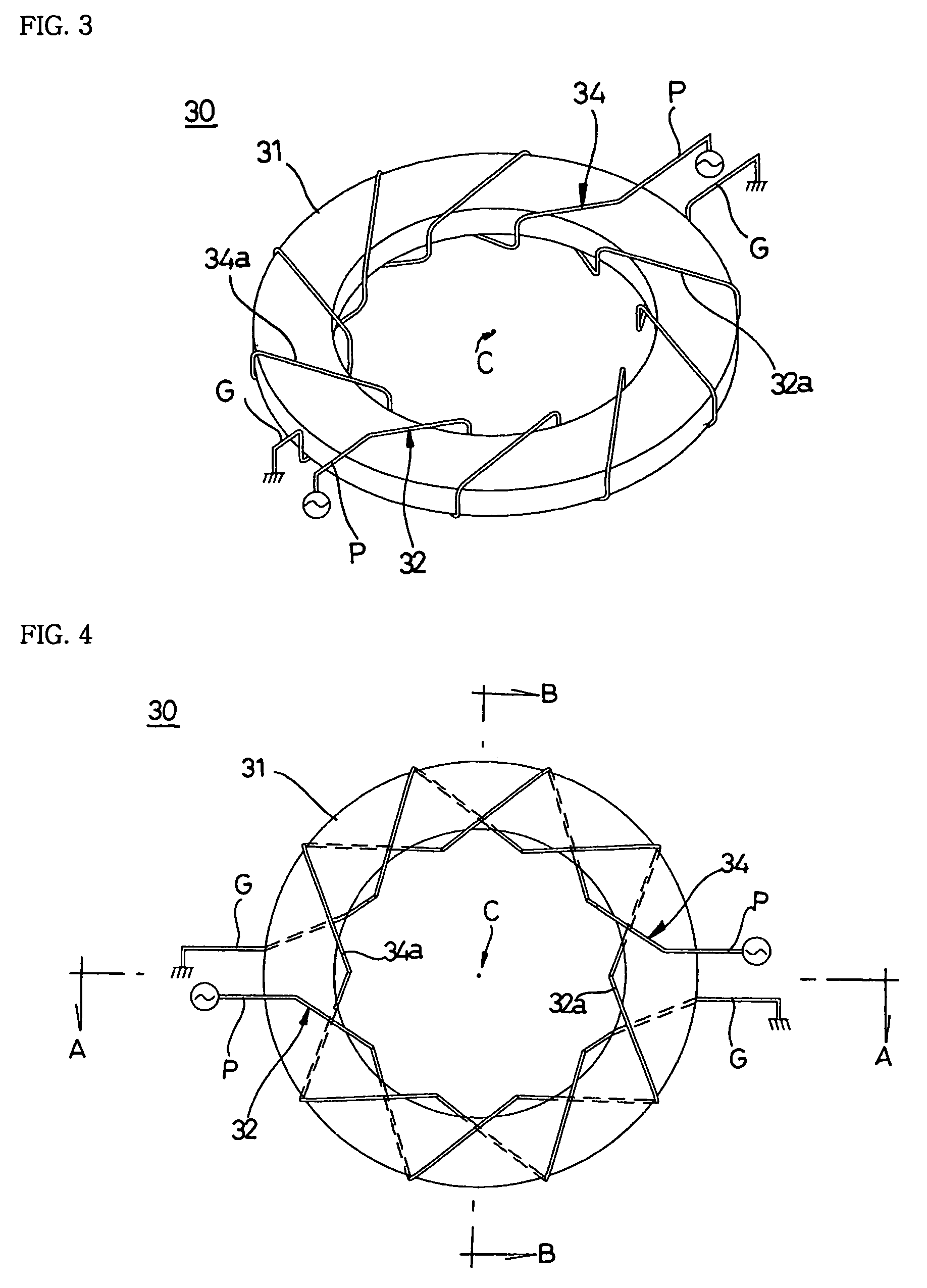
[0033]FIG. 1 is a cross-sectional view of a plasma generator according to an embodiment of the present invention, FIG. 2 is an equivalent circuit diagram of the plasma generator according to an embodiment of the present invention, FIG. 3 illustrates the structure of an antenna of the plasma generator according to an embodiment of the present invention, and FIG. 4 is a plan view of the antenna of the plasma generator according to an embodiment of the present invention.

[0034]As shown in FIG. 1, the plasma generator according to the present invention is basically constructed of an inductively coupled plasma generator. That is, the plasma generator according to the present invention includes a chamber 10 having a gas inlet 11 through which a reaction gas is supplied, a vacuum pump 12 for maintaining the inside of the chamber vacuum, and a gas outlet 13 thro...


PUM

PropertyMeasurementUnit
frequencyaaaaaaaaaa
frequencyaaaaaaaaaa
angleaaaaaaaaaa

Abstract

An inductively coupled plasma generator having a lower aspect ratio reaction gas, comprising a chamber having a gas inlet through which a reaction gas is supplied, a vacuum pump for maintaining the inside of the chamber vacuum and a gas outlet for exhausting the reaction gas after completion of the reaction, a chuck for mounting a target material to be processed inside the chamber, and an antenna to which high-frequency power is applied, the antenna provided at the upper and lateral portions of the chamber, wherein the antenna has parallel antenna elements in which a discharge of a high frequency can be allowed and impedance is low to ensure a low electron temperature, the antenna is disposed such that a powered end of each of the antenna elements and a ground end of each of the antenna elements opposite to the powered end are symmetrical in view of the center of an imaginary circle formed by the antenna to establish rotation symmetry of plasma density profiles, the antenna elements are twisted in a helical manner, and the powered end of each of the antenna elements is positioned to be far from the chamber and the ground end of each of the antenna elements is positioned to be close to the chamber, thereby compensating for a drop in the plasma density due to ion loss occurring at the powered end.

Description

[0001]This application is a continuation of pending International Patent Application No. PCT / KR2002 / 001409 filed Jul. 26, 2002, which designates the United States.FIELD OF THE INVENTION[0002]The present invention relates to an inductively coupled plasma generator having a lower aspect ratio, and more particularly, to an inductively coupled plasma generator having a lower aspect ratio, which can reduce an electron temperature to be suitable for etching an oxide film, ensure high selectivity by reducing a volume of a chamber, and can accurately fabricate a large-diameter semiconductor wafer by establishing rotation symmetry of a plasma density profile and uniformly maintaining plasma densities at the peripheral and central portions of the chamber.BACKGROUND ART[0003]In fields of forming fine patterns such as semiconductor wafers or flat panel display devices, plasma is generated and various surface treatments including dry etching, chemical vapor deposition, sputtering and the like, a...

Claims


Application Information

Patent Timeline
Patent Type & Authority Patents(United States)
IPC IPC(8): H01J7/24B44C1/22C23C16/00H01J37/32H01L21/3065H05H1/24H05H1/46
CPCH05H1/46H01J37/321
Inventor LEE, YONG-KWANJUNG, WON-BONGLEE, SANG-WONUHM, SAE-HOONLEE, DONG-SEOK
Owner SEMES CO LTD
Why Eureka
Try Eureka